|
What exactly is a resistor, and how do identify
theses things?
A resistor is
a passive two-terminal electrical component that implements electrical resistance as a circuit element. In
electronic circuits, resistors are used to reduce current flow, adjust signal levels, to divide
voltages, bias active elements, and terminate transmission lines, among other uses.
The resistor is a passive device and doesn't do anything actively to your circuit.
Its actually a pretty boring device. If you add some voltage to it, nothing really happens.
Well, maybe it gets warm, but thats it. BUT, by using resistors, you can
design your circuit to have the currents and voltages that you want to
use to control or limit active devices. So, by itself it may be
boring, but in a circuit the active components performance is dictated by
the resistor value. This why the resistor gives the designer control over
his circuits!
Most through hole resistors
(AKA axial or leaded) in the 2 watt or below have stripes all around
denoting the value. There are no stripes warning you of the power
level. In time you can estimate that by looking at the size of the
resistor. If you look at antique resistors, they may be the size of a
modern 10 watt resistor, so be cautious. However, the size for
performance does not matter. What I mean is if you use a 100 watt
resistor in place of a 1/2 watt it will do the same thing, and have no
effect on your circuit. If you replace a 100 watt with a lower watt
resistor of the same value, then you will burn out the resistor. So
you can always go higher in watts. I recommend the 2-3 watt resistors
for unknown power levels in antique devices. This goes for most of
your circuits, but not always for power circuits, like power supply or
amplifier circuits.
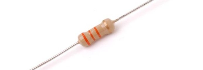
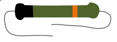
These are examples of
modern, vintage, and some antique 1/2 watt resistors:
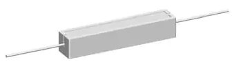
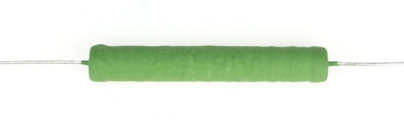
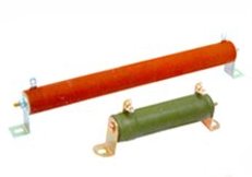
These are a few examples of 10 watt
resistors:
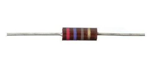
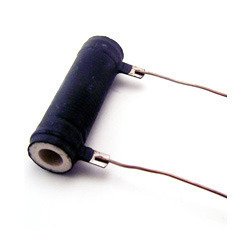
This is an example of
an antique resistors (AKA Dog Bone resistors):
Reading Resitor Codes:
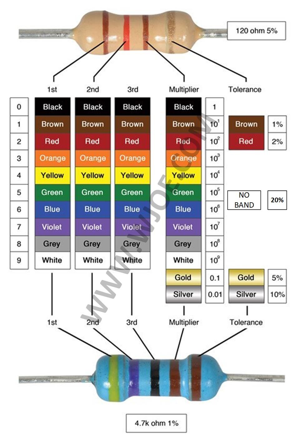
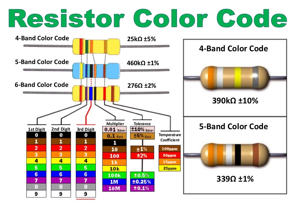
Let's start with modern resistors
that are marked with stripes. The color code is universal and applies
to most electronic and electrical devices through the ages. As well as
wire and capacitors. Take a look at the table below. This is a visual
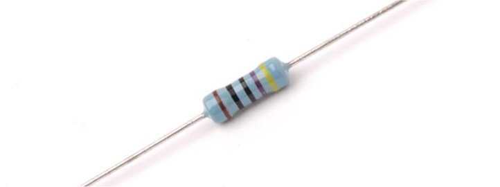
example, but not for all of them. Some resistors print the numbers on
the body. the resistor shown near the bottom is a precision type, used
mostly in the military and medical industries. Or used where 1% or
better tolerance is required. These resistors add a third value color
and is broken down to be used for more accurate resistance. If the
third band was red for instance, then the value below would be
4.72K.
One more note about tolerance
markings.
Antique resistors did
not mark for tolerance in most cases. I am sure there are exceptions,
but I haven't noticed. Older or vintage resistors would leave off the forth
band indicating a 20% tolarance. I do see these quite often when
working on vintage electronics. I'm not sure you can purchase new
resistors with a 20% tolerance. I have observed tighter tolerance resistors have become
more main stay in the market and cheaper as time goes on.
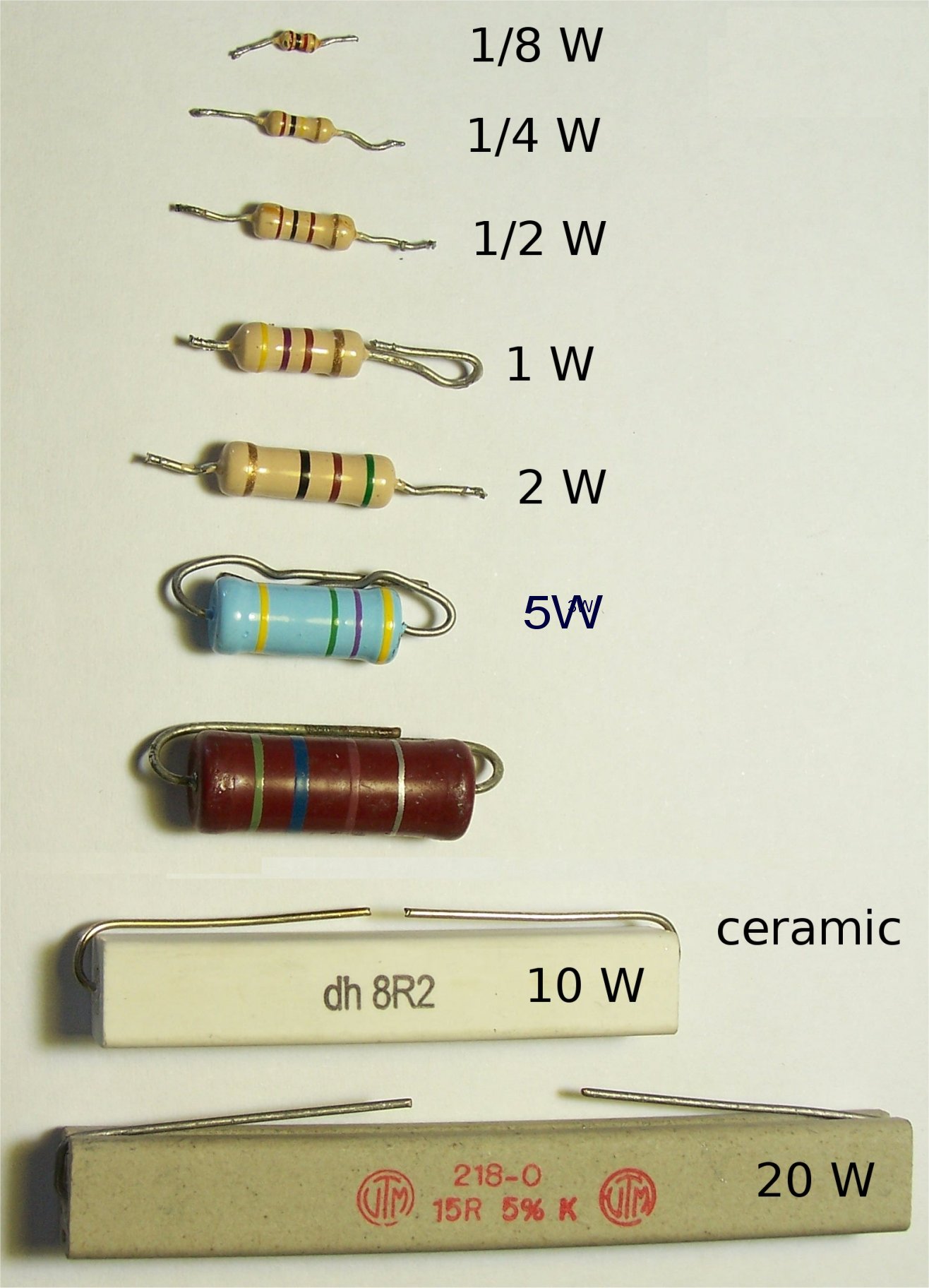
We spoke earlier about trying to calculate the
wattage of a resistor by size. The picture below was pulled from a
google search, and does a great job lining these up. This isn't always
correct because the older resistors were bigger than today's even
though the power (wattage) is equal. The chart below shows a size
comparison for reference. This is not to scale but is informative.
There are too many variations to show them all.
|
|
Decoding
Resistors:
|
|
The 4 band
resistors are the most common of all. You get the two value
numbers, then a multiplier, and the tolerance band.
The 5 band are precision
type, and usually offer tight tolerance with a more precise
resistance value. Such as 4.99K rather than 5.0k. You get three
value bands, then a multiplier, and a tolerance band.
The six
band type are exactly like the 5 band type except they add a
temperature coefficient value band. This is used when temperature
changes must be taken into account with the circuit. The temp
changing will affect the actual value. If you need to be within
1% between 30 F and 90F then your going to need to order
resistors that can compensate or stabilize during the change. These are
rated as parts per million tested per military specs. They just can not
test everyone for temperature coefficient value when producing Millions of them at
a time. |
|
|
Resistor With Printed
Information:
By
this time, you should realize the color code is pretty universal.
Decoding may change from device to device, but colors always
represents the same numbers.
In most
cases power resistors have numbers printed on the body of the device.
This is due to their size? I believe. In any case these may be coded
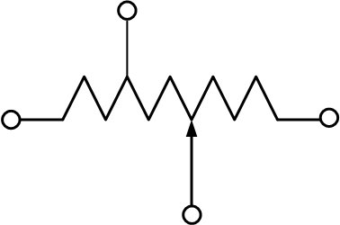
as well. There is also a
letter or two involved before or after the numbers. This is a
tolerance code, or in some cases a multiplier designation. Most are to
(K) 10% or (J) 5% but certainly not limited to just these two. In some
cases, they will just tell you. There are also cases where they don't
tell you. The next three sections will point out one by one the
difference. The last image shows us all the known tolerance letter
designations.
|
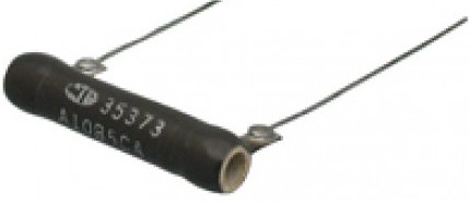
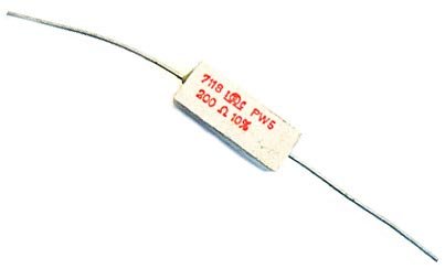
This example is pretty straight forward, and is common. The
first line shows a part number then a coded way to tell you this
is a 5 watt resistor.
The second line tells us this is a 200 ohm 10% tolerance
resistor. |
 |
|
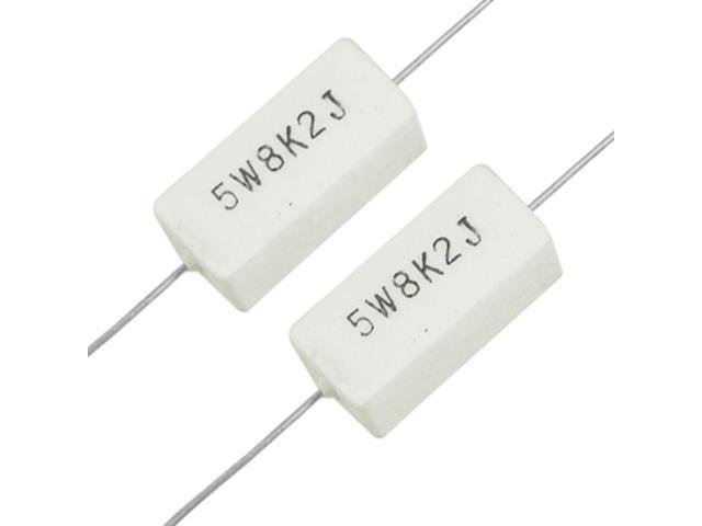
In this example there is no part numbers, and a K as
well as a J in the line of charactors. These are read in a
straight line, meaning one section at a time. Do not confuse the
K with the J. If you break this down you would start with the
5W, then the 8K2, then the J. There is a set format, and it
takes time to get used to it. Let's break this down:
5W: 5 watt resistor
8K2: is another way to tell you this is an 8.2K resistor. If
there was an R, then it would be an 8.2 ohm. If there was an M,
then you guessed it! Its an 8.2M resistor.
J: This is the tolerance designation, and tells us its a 5%
part. |
 |
|
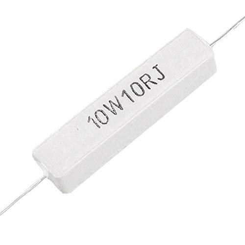
This is very much like the one above, however the information
is varied slightly.
This reads as. 10 watt, 10 ohm, 5% resistor.
Like before when you see an R after the value, or in between
then its value is in ohms.
If you see a K then its in K ohms.
If this was 10R5, then it would be a 10.5 ohm resistor.
The tolerance is usually the last designation. |
 |
|
As you can see there is more than
just two letter designations for tolerance. The most common are
J and K, but any of these could be used. I have never seen P
or Z on a resistor. However, there are many old capacitors with this
kind of tolerance. The D is a special designation for capacitors. This
makes sense since this is a universal color code
that applies to other types of components, like
capacitors.
|
 |
Resistor TYPES:
There are many types of resistors
from fixed to variable, adjustable, tapped, fixed tapped, rheostats. Then
we have many materials they can be made of. Like metal film, carbon,
wire wound, and others. We will cover some of the types here to
keep it as simple as we can. For antique electronics wire wound were
the most common. For vintage electronics carbon seem to be the most
common. Most wire wound resistors tend to be high power types above 2
watts. I am sure prices, or cost was the determining factor. However,
in some cases you want to use a certain material in your design. I
think for this exercise we are not concerned with new technologies
when it comes to resistors. We will stick with carbon and wire wound
as far as materials go.
AXIAL/RADIAL: I think we covered the
general fixed axial resistors. This is simply a single device with one
unchangeable (fixed) resistance, and two leads coming from each end.
At this point we have not shown any radial type, but they were seldom
used in antique electronics. Used in some high power circuits in
vintage electronics, like amplifiers. All aspects concerning power,
value, and tolerance is exactly the same. Just the orientation of the
leads are different. The leads or connection points can come from
anywhere but the sides. Meaning the top, ends, middle, bottom. A few
examples shown below will help you determine
this.
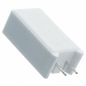
Tapped
Variable: I think we covered the general fixed axial
resistors. This is simply a single device with one unchangeable
(fixed) resistance, and two leads coming from each end. At this point
we have not shown any radial type, but they were seldom used in
antique electronics. Used in some high power circuits in vintage
electronics, like amplifiers. All aspects concerning power, value, and
tolerance is exactly the same. Just the orientation of the leads. The
leads or connection points can come from anywhere but the sides.
Meaning the top, ends, middle, bottom. A few examples shown below will
help you determine this.
This resistor is usually a
radial type to make it ergonomically correct. Meaning this makes
adjusting them easier once in a circuit or mounted to a chassis.
Mostly found in antique electronics for many reasons. You would use
these to make adjustments after the device was built. In most cases
its used to compensate for circuit tolerances, or drift as the device
warms up. Also, can be used as a voltage divider to supply certain
circuits with certain voltages. Keep in mind antique devices had very
high tolerances with components than later devices. Plus, more drift
due to extreme heat and electrical changes of the tubes. As electronic
components and design progressed, less and less of these resistors
were used.
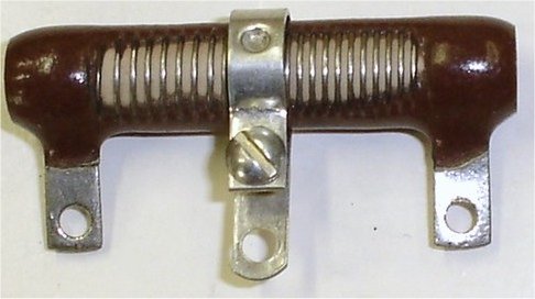
The center tap, or adjustment
lead is usually loosened with a screw, and has a bump out that touches
exposed wires alone the resistor. Once loose the tap can be moved back
and forth along the internal wires changing the resistance at the tap
ONLY. The actual or fixed resistance does not change. These can come
in any fixed resistance, and in many cases the adjustment is limited
to a certain part of the resistor. Let's take a 10K version. From the
two outside leads it will read 10K ideally. One end to the center tap
may only have a range of 3k to 8K.
What does Ideal mean: Simply
put, IN THE PERFECT WORLD It was designed and build to be a specific
value.
Resistors like most of
us drift over time. This is where wire wound performs the best. They
tend not to drift unless heated beyond specs. This is where they are not
at their best. Used properly they will be pretty stable after many
years. Once use incorrectly the resistance can change dramatically.
For manufacturing, a tolerance is put in place so they can
be manufactured at less expense. Like everything else, cost is always
a factor. So a device with 20% tolerance is generally cheaper
to purchase than one with 10% or better. Today they make millions at a
time, then test them before they are marked. The resistors that are
within 1% are marked 1% and so-on. Yet the 1% will cost more even
though they came from the same run. The point is, they don't make a 1%
run. They make a run and sort it out afterwards.
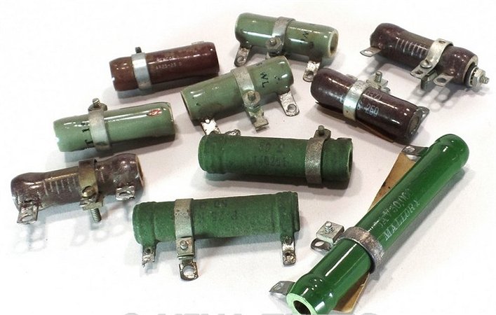
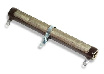
Below are a few examples for
review.
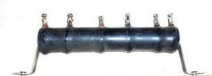
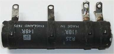
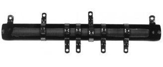
Multi-tapped
Resistors: Are also fixed, but not adjustable like the fixed
adjustable type. These can have multiple taps, not just one. The
multiple tapped usually have more than one tap, although there are
many with just one tap.
There are used to simplify
the manufacturing build, or space, or cost. Again, cost is always
the first concern when building a product. You can get one 20
watt resistor that needs to be tied to one place and do many things at the
same time. They can also be used to make more space in a smaller
chassis. The most common use in antique devices is power distribution.
They tie one end to B+ then tap off many voltages from that source.
Again, like the fixed tapped resistor, these are primarily found in
power resistor category over 3 watts. I have found that when these go
bad its usually one section. Just a tip: If this happens then just
replace that one section with a standard resistor.
As far as values,
power, and marking goes? Don't expect much, because they are not
always marked. In many cases I see a part number rather than
specifications. If your repairing something then your probably using
the schematic, or parts list.
The next photo's shows
us some examples.
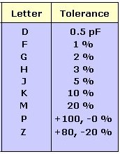
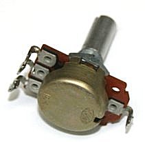
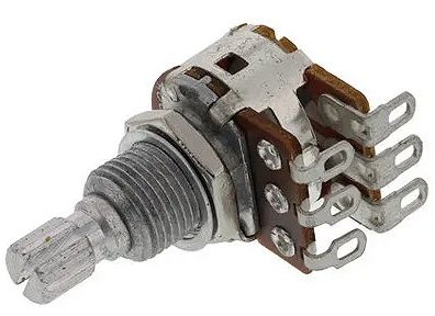
Variable/potentiometer/rheostat
Resistors:
This is very commonly used for volume and tone controls. They are
called variable resistors, pots, even rheostats depending on how they
are wired. These are actually called Potentiometers. They are used for
many purposes in a circuit as well. Calibration, compensation,
limiting, current limiter (rheostats), voltage dividers, and more!
This is a
fixed resistor with a tap (wiper) that is moved across the entire
resistor. So it has three leads, one connected to the wiper, and the
other two connected to the resistor. These also have power ratings,
and are marked very similar to the power resistors.
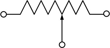
Let's
discuss a rheostat first, just to get that out of the way. The real
physical different between a rheostat and potentiometer is the way
they are wired. A true rheostat would have two leads, or the wiper
tied permanently to one of the resistor leads. Any potentiometer can
be a rheostat just by connecting the wiper lead to one of the resistor
leads. Below are the schematic diagrams of each to help
clarify.
|
Potentiometer |
|
Rheostat |
|
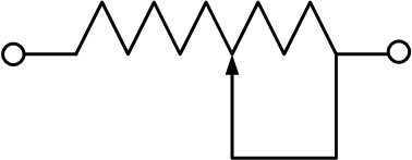
Tapped |
|
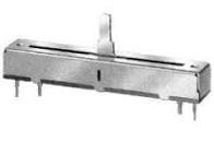
Potentiometers also have many physical types, such as slide, trimmer, dual
to quad, and tapped. Although the general idea and functionality are
the same.
A tapped potentiometer would
have a forth lead from somewhere in the body. This has two fixed
resistors in one, but the tap is referenced to the internal
resistance, and not connected to the wiper. The tap can be anywhere
within the resistor. It's usually near the center of the resistance
value. So on a 10K ohm potentiometer, the tap is most likely in the 3
- 8K area.
A slider potentiometer is
like any other in the fact that it does vary resistance. The only
difference is the physical means. A slider moves back and forth, where
others move in a circular fashion.
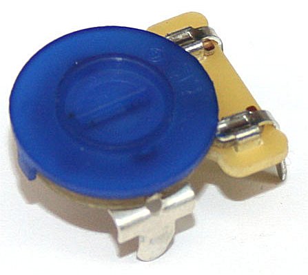
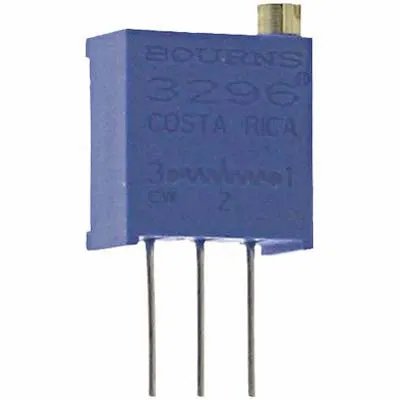
What we call Trim Pots can
vary within themselves. However, they are usually small and have an
opening for a small screwdriver to set the resistance. They are not
made for continuous use. They are used in circuits to make a
calibration or set point adjustment. These come with multiple turns as
well. Most potentiometers are a single turn, but many trimmers can be
10 turns. This why they are great for set points and calibrations. 10
turns will give you a much finer and slower adjustment for
accuracy.
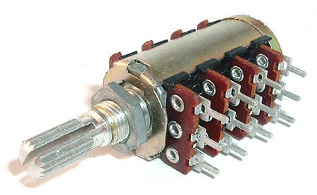
Dual or Quad potentiometers
are exactly like any other EXCEPT they have more than one variable
resistor internally. These can come as slider or single turn. I have
never seen a dual or quad multi-turn potentiometers, however it
wouldn't surprise me. These can also be tapped.
 |
 |
 |
 |
 |
 |
|
TAPPED |
SLIDER |
TRIMMER Single turn |
TRIMMER 10 turn |
DUAL |
QUAD |
How do we USE Resistors?
Let's start
with ohms law, and let's start with a chart! I'm not going to cover
ohms law for this article, but at least show you what it takes to
figure out resistance or how to figure out the resistance you need in
a circuit. There are a couple versions of the chart I just mentioned.
The first is the simple version and the one we will focus on. The
second is a reference for you. As you can see they are quite
different, and similar. The Pie represents a multiple (horizontal
lines) or a division (vertical line). So, P would be divided by
either
|
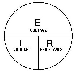
This chart is what we will talk
about and adhere to. Basically, this represents three formulas
just as it is depicted. Voltage can be represented as "V" or
"E". I have no idea why, but that's what it is. Then "I"
represents current and AMPS, again I don't know why since we
measure amps as "A". The "R" for resistance is the only one that
makes sense. to simplify we will break it down the basic three
formulas.
E =
I x R
R = E / I or E over I
I = E / r or E over R
When one letter is over another you divide, when one is side
by side you multiply.
|
 |
|
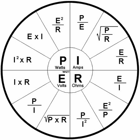
This chart is very much like the first chart, but offers many ways
to figure out the same parameters. This chart also adds "P" wich
stands for power (watts). You will always need at least two
electrical parameters, but you wont always have the same two.
lets look at R (resistance). You can figure this out with
(power and current) or (power and voltage) or (current and
voltage). |
 |
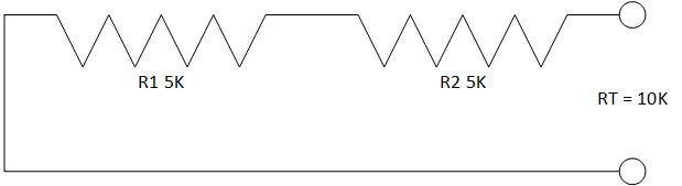
Use up the resistor we have:
Resistors
can be added or divided, and certain values can be made by
combining multiple resistors. You can also use resistors to compensate
for power. If you have a 2 watt load you can use two 1 watt resistors
to carry that load, but the value of each resistor would have to
change. These circuits are called series or parallel resistance. You can
also use them in a series-parallel design. Below are examples starting
with series resistance, then parallel, then series-parallel. We will make
the "RT" Resistance total, the same in all three using different
resistors. Let pretend that's the only resistors you don't have are
10K, and your in a hurry to get this
done.
|
|
|
|
|
Series Circuit: They add up, RT = R1 + R2
The power rating for this configuration would only be
as high as the lowest power value. So if R1 is a 1
watt and R2 is a 2 watt, then the total wattage only 1
watt. |
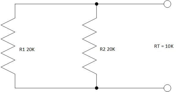
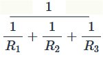
Parallel Circuit: They divide when RT = R1/# resistors.
RT = R1/2. This only works when all the resistors are
the same value. When they are not, we need to use the equation shown
below. Power in this configuration can be shared. SO, if both
resistors were 1 watt, then the total power rateing will be 2
watts.
|
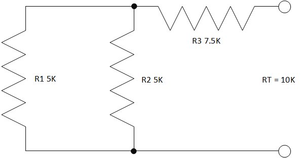
Series-Parallel Circuit: All the same rules and
calculations apply. The trick is to separate the two types.
Calculate the parallel resistance (R1 and R2) first, then add
that resistance to the series resistor R3.
Power
is unique in this configuration though. In this case the series
resistor OR the parallel is going to dictate the max power
value. However, you can mix up power values. R1 and R2 can be 1
watt, and if R3 is a 2 watt then you have a 2 watt circuit. BUT
if R3 is a 1 watt, then you have a one watt circuit. This works
in reverse too. Let's say R1 and R2 are 1/2 watt, and R3 is a 2
watt resistor. This means you still limited to a 1 watt circuit.
Since we separate to calculate, we have to calculate all
parameters. For power we always use the smallest value as our
MAX
power. |
Sooooo, let's re-cap! This article was not intended
to go over Ohms Law, but rather a perspective for information about
resistors and their use. Safety is another concern so power and its
role with resistors was added. Always be safe! You can always Google
Ohms Law Calculators. They are easy and useful, and I use them all the
time. I hope you found this informative and let's hope it has some
influence with your testing, troubleshooting, and repairs.
Disclaimer: The information
contained within this website www.wjoe.com, or any affiliate, is
derived from theoretical information based on experience and knowledge
obtained in experience. The reader "you", are ultimately responsible
for any and all information used from this site. Any damage, or any
consequences you experience from this information is solely your
responsibility. This information is a free service, so please enjoy
it! Any other use, retention, dissemination, editing, selling, or
copying anything from this site, for any intent is strictly
prohibited. Unless you obtain written permission by me at
joe@wjoe.com. Any information on this web site is owned by myself and
is intended to aid you in your research about Antique or Vintage
capacitors. Please enjoy!!!!!!
Written by WJOE Radio 08/10/96,
LLC Edited
11/07/19
|