Welcome to W J O E RADIO, Taking radio from the past into the new Millennium!
![]()
1933 Philco 18/118 Shadow Meter UPDATED 01/07/16
|
1955 Oldsmobile radio |
1932 Zenith ??? |
U.S. Gloritone 3072 |
RCA 128 |
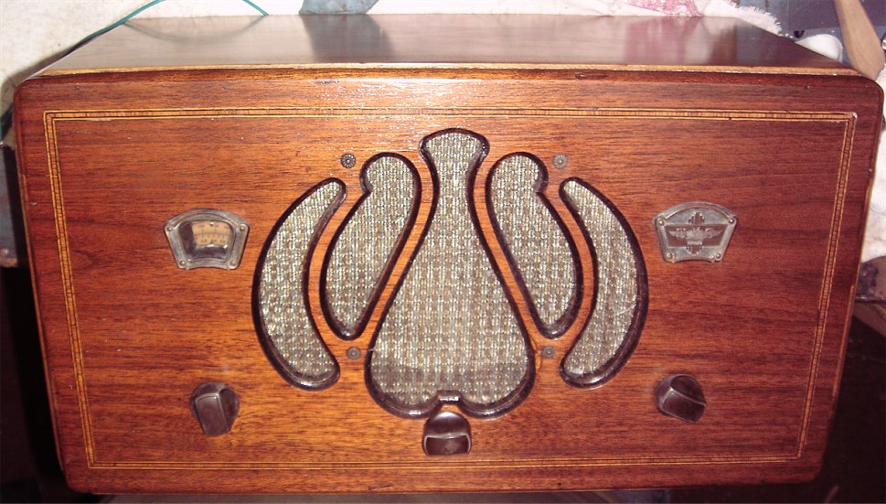
Philco 20A |
Philco 20A
04/22/17
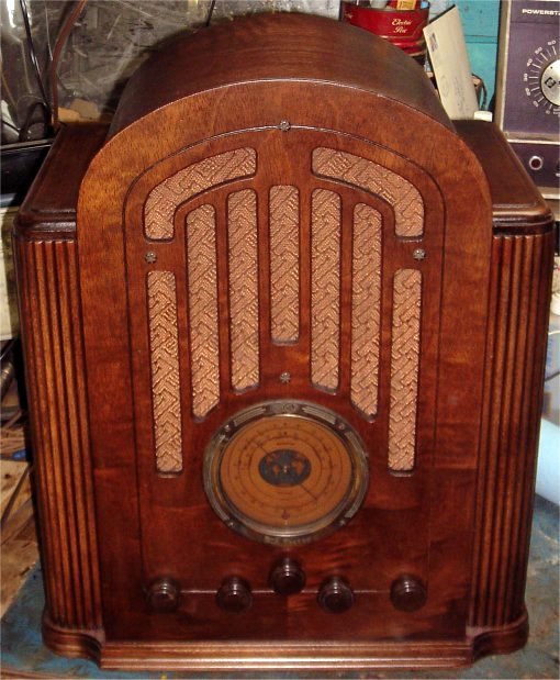
This is not the plain variety Philco 20. This has some great cabinet features that makes it stand out from other versions.
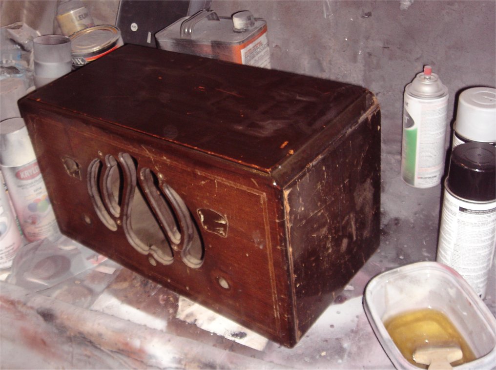
I purchased this at a thrift store for $65 because it looks great. The cabinet is amazing for something made in the thirties. The seller is a radio collector so I knew what I was in for when it came to electrical restoration. Been doing this long enough to know there are major issues with the electronics if a radio collector is selling it at a good price. I didn't cath the picture before I started to strip, but there isnt anything to tell you anyway. Like I said the cabinet was in great shape. The only issue worth a mention is what looks like a burn mark on one side. This sanded out with ease. What you see below is after the stripping and sanding down to 0000 metal pad. Still needs a little tweaking.
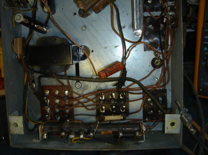
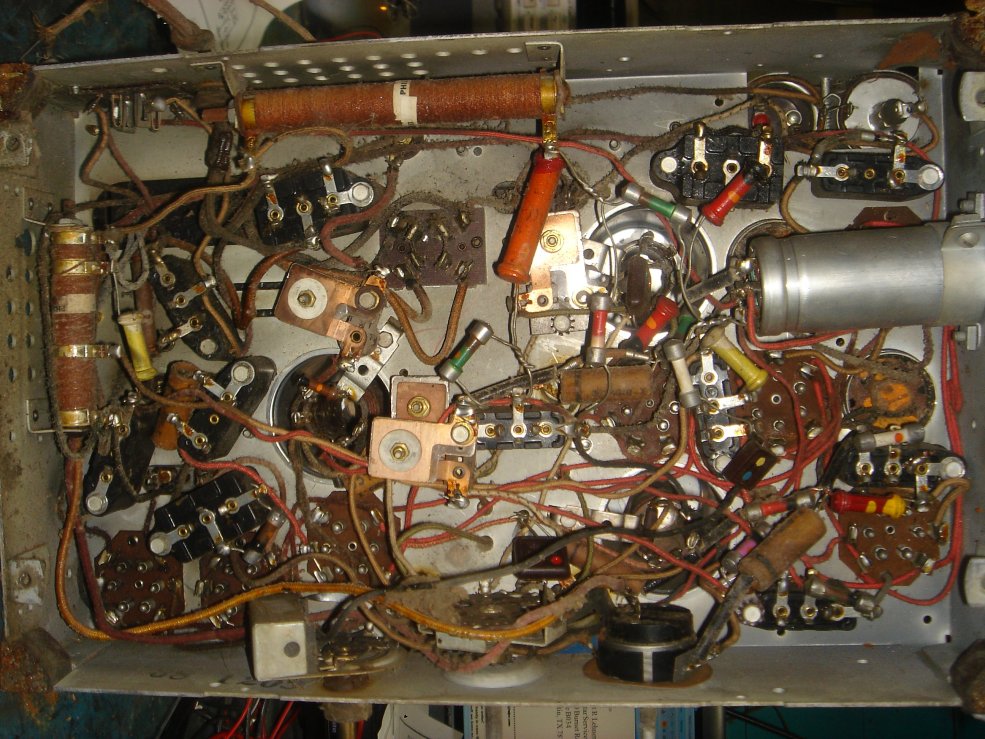
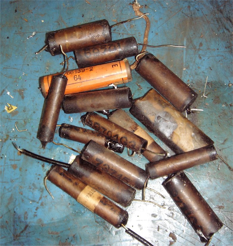
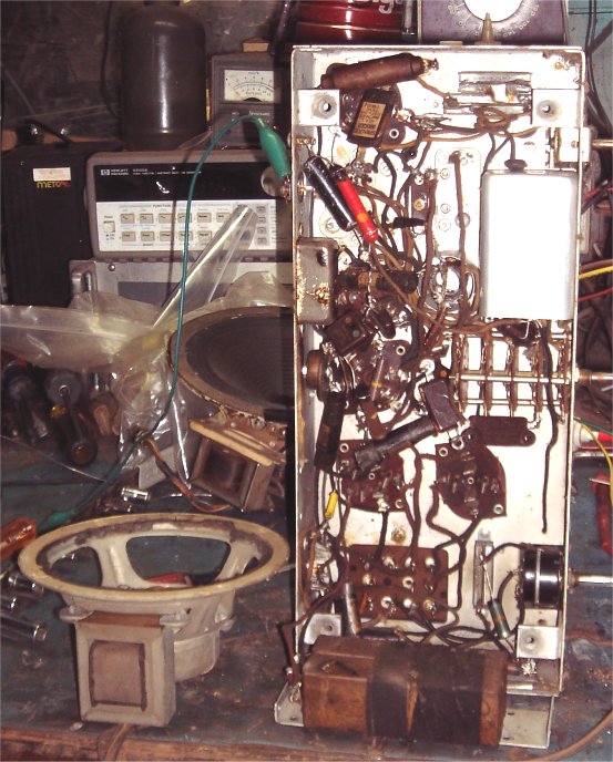
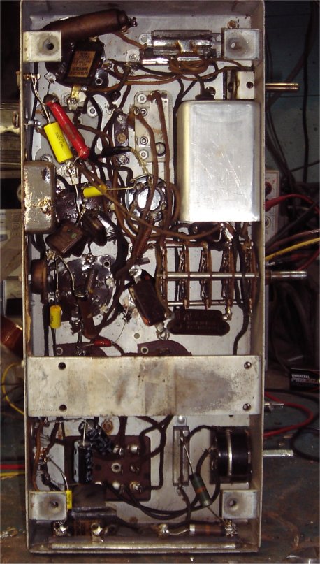
At this time, (as you can see) the chassis has been removed. This wasn't as bad as I thought it would be, but there are many issues. Someone replaced and audio transformer BADLY. Only one screw, and it was loose. They also replaced a few components BADLY. Take a look at the orange capacitor in the first picture, and the tape under it. the AC line connections are terible. Soldered cold and frayed wires all over. At least they tried to contain it with tape. The worst thing they did was cut components to test them and/or the circuits. They cut them then soldered them back on with out a loop. This includes wires to the bakelite cap holders.
I don't work that way so it had to go. This was not to much of a problem since I had to rebuild all the bakelite cap holders anyway! I started with replacing the AC line cord, and installing the correct hardware to secure it safely. Removing all the tape, and soldering it correctly. Then I power up to found the bus voltage at 270 volts with about 50 volts of ripple. This is typical, but it tells me the transformer and 80 tube is good. This has a cap bank from 1930 in it, so replaceing that was not an option. We sell the small axial, and this needed three of them. A little rewire and common sense I got that supply back up to 420 volts with almost no ripple.
Next step is to see whats not working with the use of a signal tracer. Turns out nothing is working, except the power supply bus voltage. Tested all the tubes only to find out one of the audio output tubes was very weak, but certainly not the problem. Knowing this was cheap and came from a dealer we need to check the coils. Like every radio I purchase from a collector..............one of them was open.
04/24/17
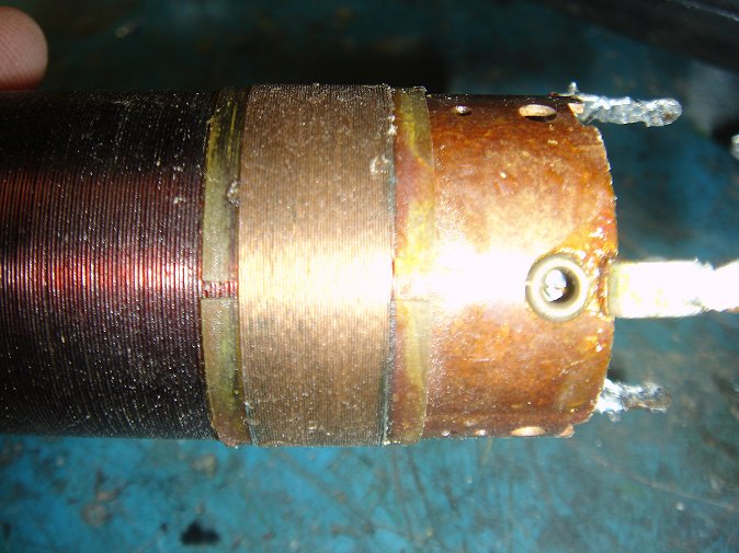
Found the open coil, and repaired it. This one was worst than average. This is typical for early Philco radio's. The wire is very thin and tends to rought out until its open. This is a dual coil. The red wire is OK the light orange wire over it is the problem. You can see the dark spots at the beginning and end of this coil. I found opens on both sides. A little teadious, but repairable just like new.
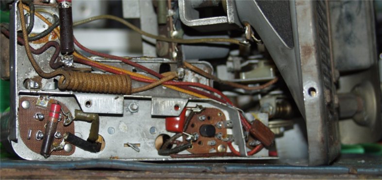
This repair put some spark into the radio, but very little. The voltage going to the RF and Osc tubes was very low. This was traced back to the large resistor network on the bottom of the chassis. This is a multi-tap high wattage resistor with one part open. I installed the correct resistor to the open portion only. Now we get some signal we can hear with the signal tracer only. Nothing is coming out of the speaker. This is a perfect start. At least we know something has a signal and life is good!
04/29/2017
Spent a this weekend taking out and rebuilding the bakelite capacitors.
Testing the radio every time I install a new one. There is some very low audio
now, and selectivity is better. A few more caps to go, but I figured the radio
would be working pretty good at this point. While I was pulling the bakelite
caps I was able to test the resistors. Some are close, some are 20 to 30 % off.
They will work as they are so none were replaced. I like to go through with a
resistor substitution box later to tweak and fine tune anyway.
Finally I finished all the caps except the mica, yet still low but better audio. There is some distortion as well. More probing revealed an issue with high voltage to a portion of the amplifier. Turns out the speaker field coil is open. I tried to repair it but the windings had lots of opens. I went through my parts and found a speaker of the same size. This speaker had to be re-wired with the original matching transformer and connector to work best. It did work GREAT. The original speakers are not that great anyway. The new one is from the same time period, but a much better speaker. Now we have loud clear sound, and a working chassis.
I went trhough and did some fine tuning using the resistor sub box. I used this method for years. You would be surprised how much improvement you can make changing out a few resistors.
05/01/17
Lets recap! This radio had a bad open speaker field coil. Open osc coil, open power resistor, and many capacitors. BUT a great case. Just keep in mind these are what you get with unknown from dealers. If you can get them a good price then all is good.
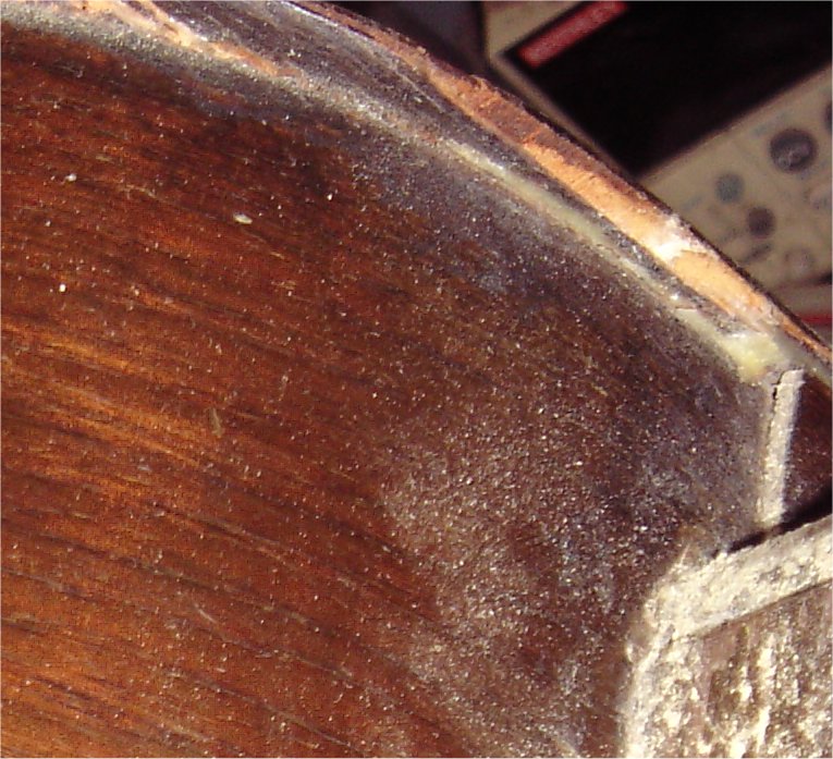
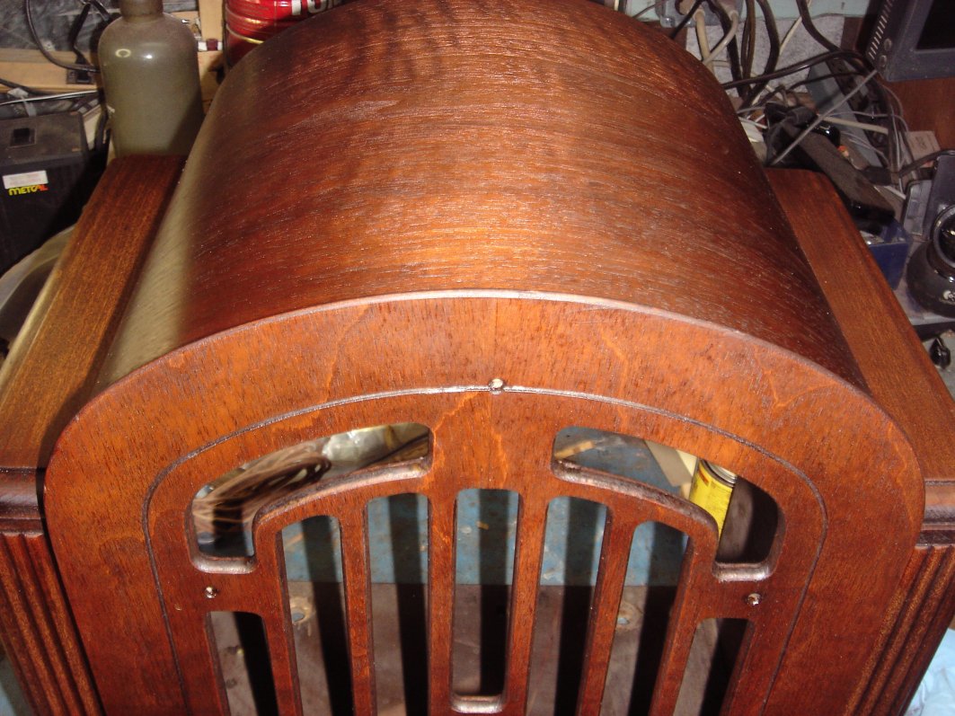
The case has been stained for the first time. this is where imperfections or mistakes are going to show thier best. This will need some light sanding and a couple corrections. Then stained again! Along the very top there is a crack where the veneer came together. You can also see the nail holes. All this is OK and came frommthe factory that way, but all the stripping and sanding brought it out. These just need a little filler and the correct stain to hide like it was done in the day. Around the knobs you can see some issues. This will be staind until it blends in better, but one the varnish is applied you wont see that anyway.
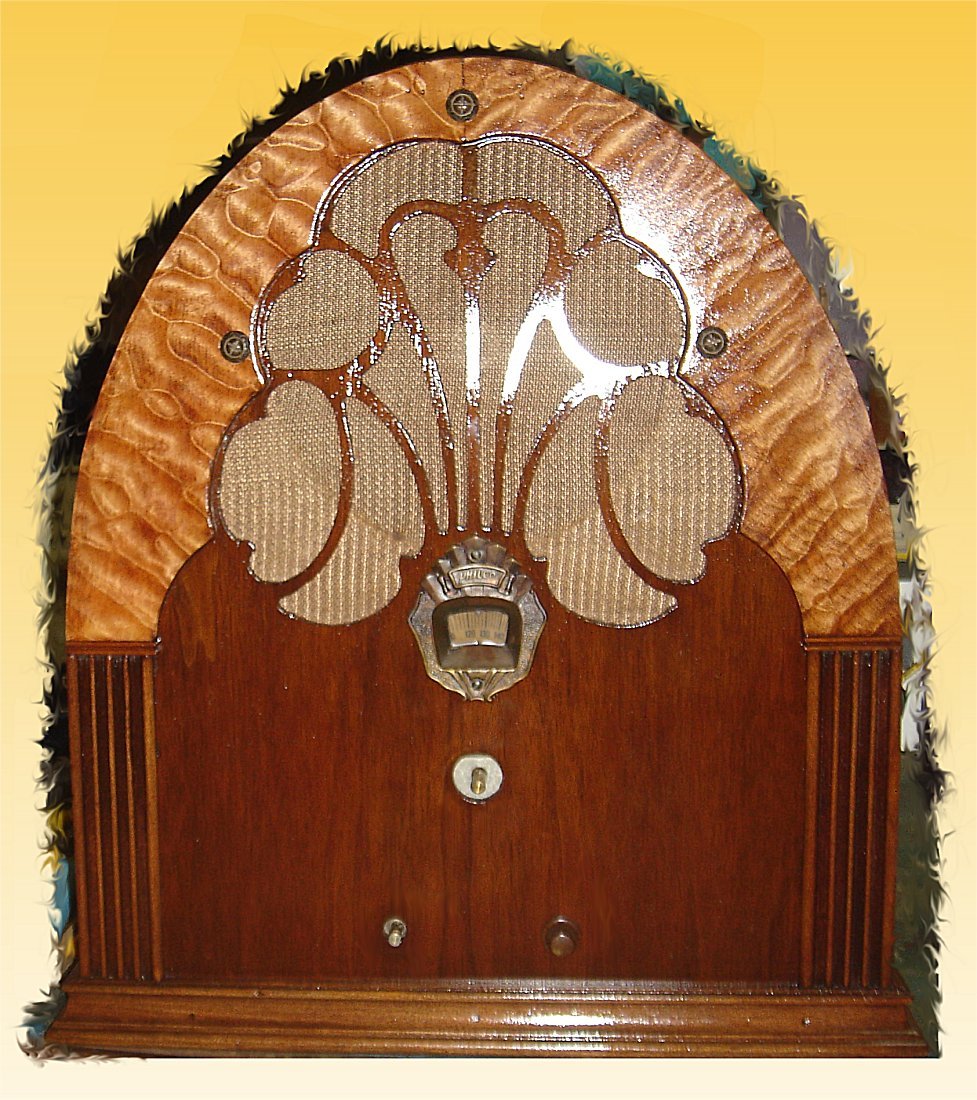
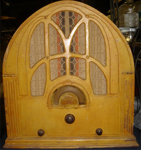
Philco 118
10/22/14 Updated 05/21/17
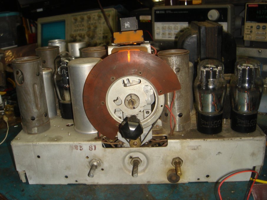
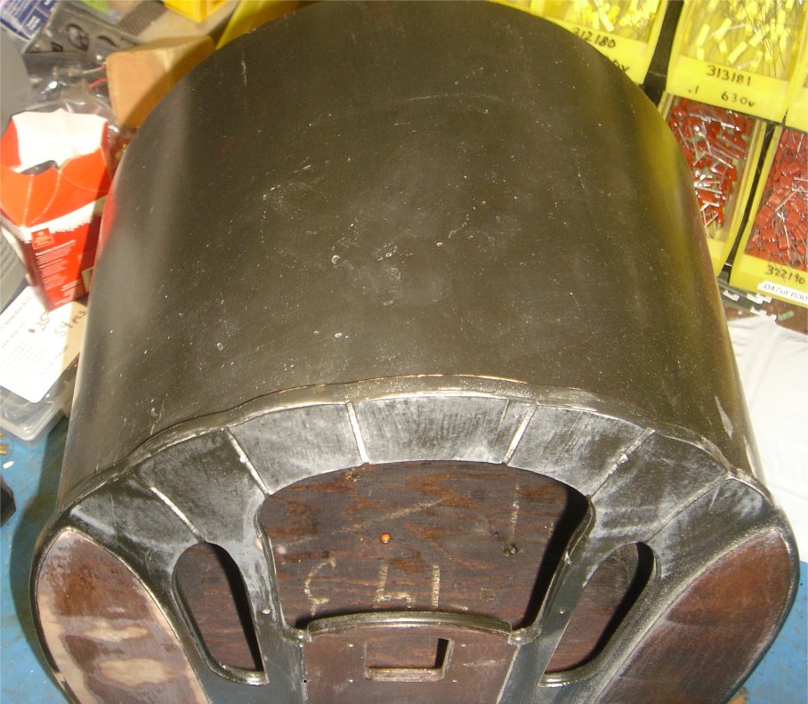
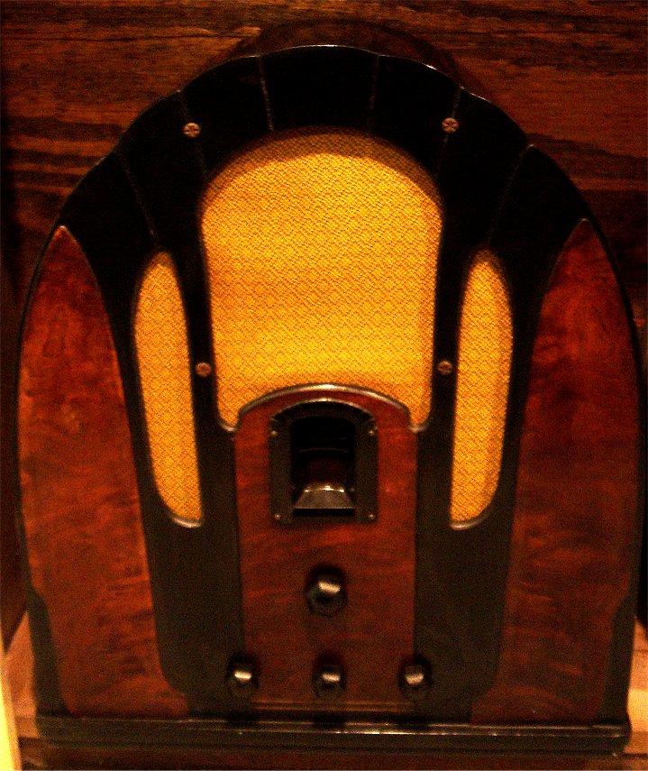
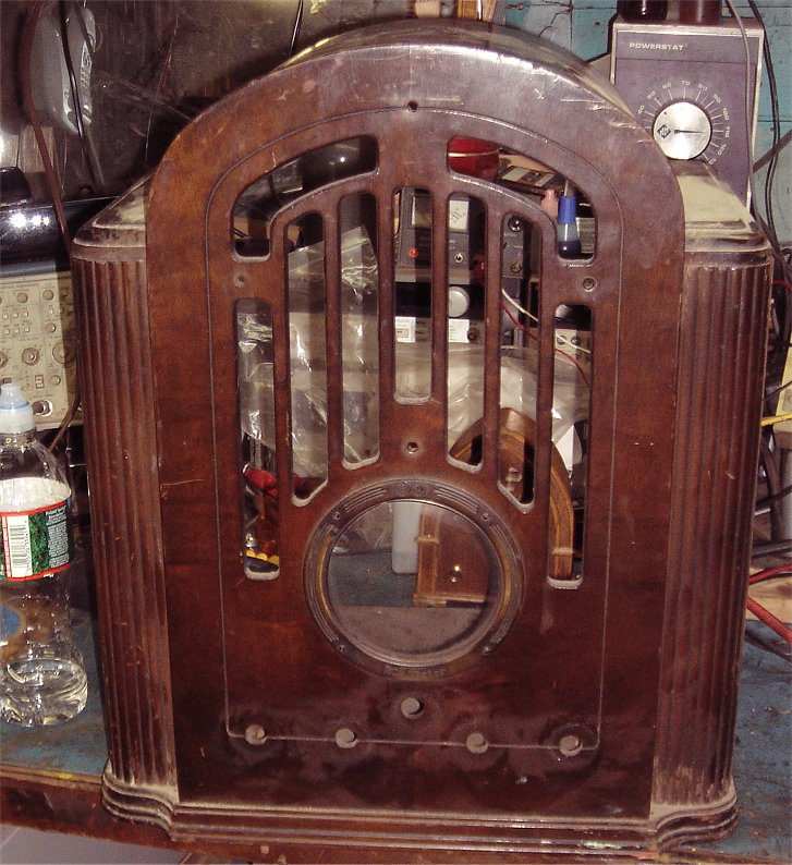
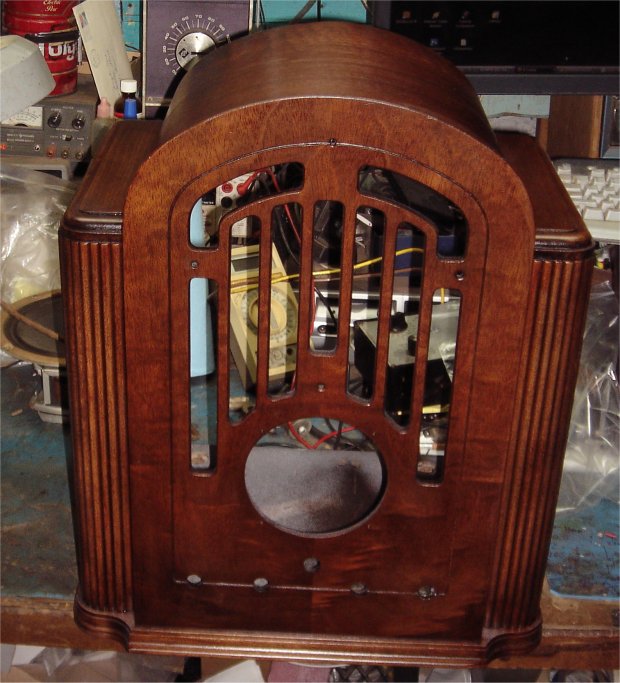
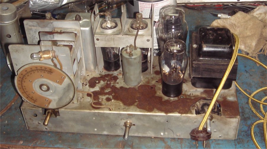
A beautiful Philco 118, 8 tube chassis with a 10 watt push/pull amp, and the Shadow Meter.
11/01/14
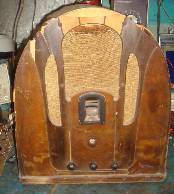
I picked this up in Harvard, MA at a flea market/antique show. Most people would consider this a basket case, BUT it calls to me! It cost me $35.00, and probably not worth it. The seller started out at $50, but I was sure $35 was to much in this condition.
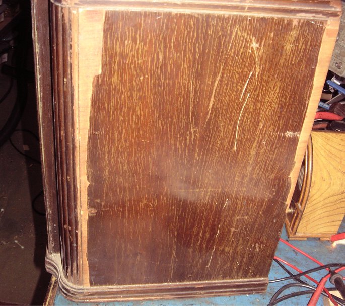
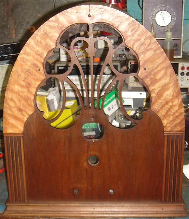
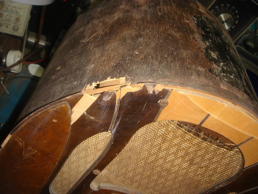
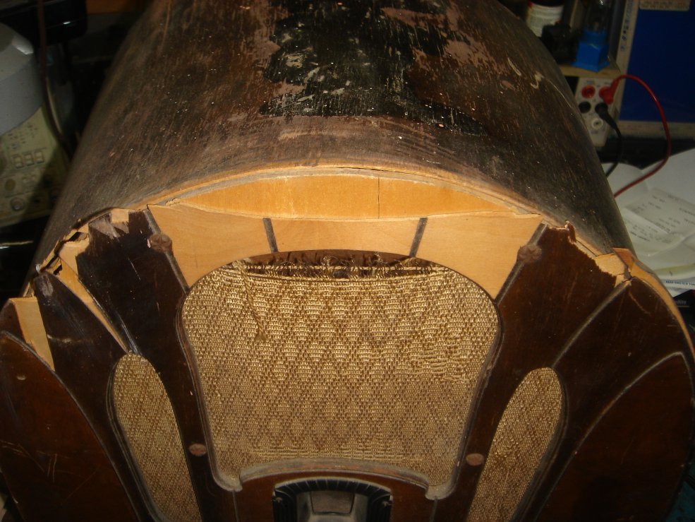
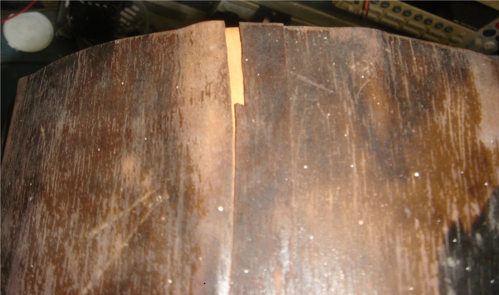
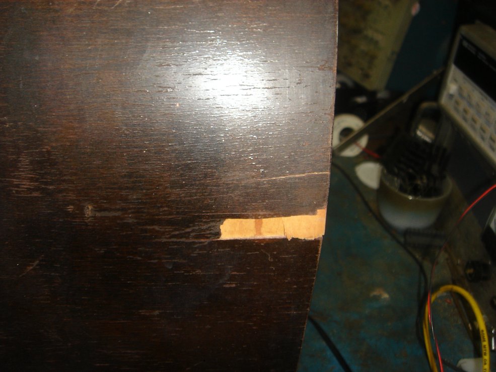
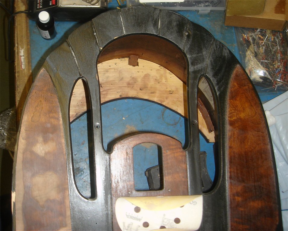
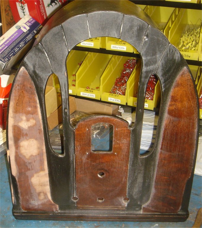
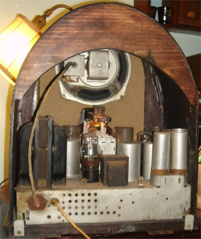
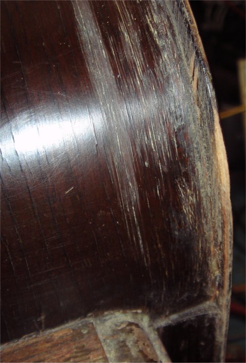
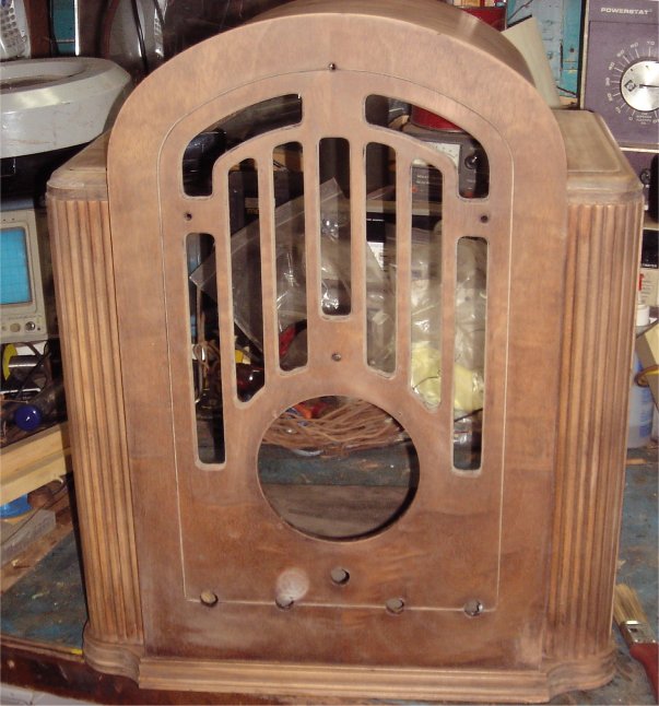
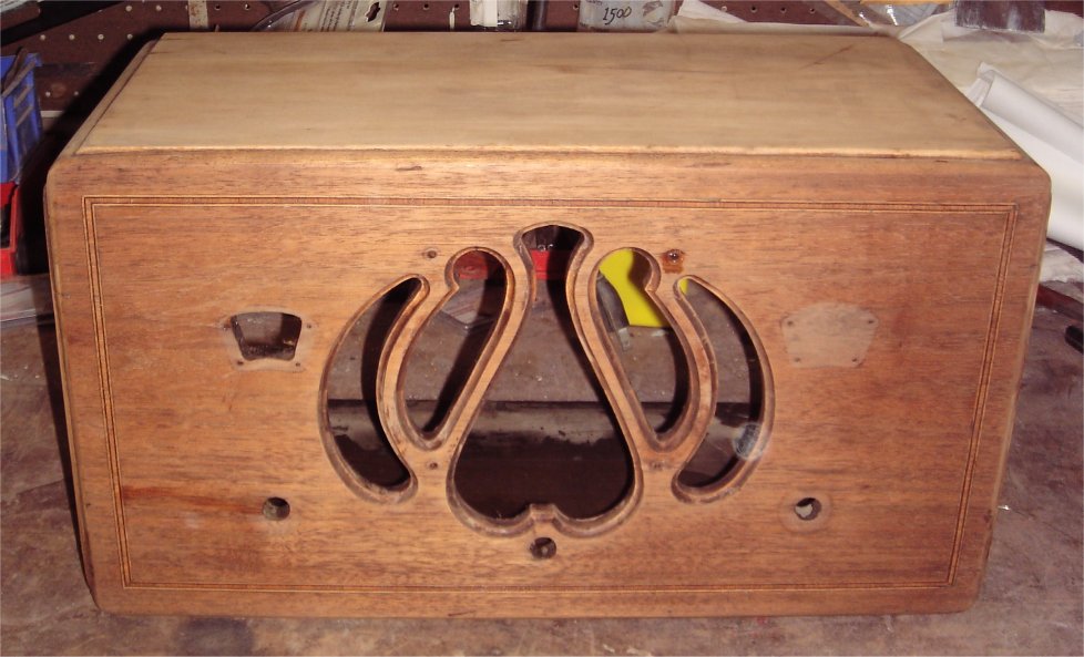
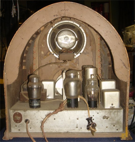
Everything is wrong with this radio! The case has been badly damaged with lots of veneer damage as well as missing the wood piece that retains the cathedral look. Look at the rear picture above and tell me what is missing. The top is all loose and cracked. The following pictures show most of the cabinet damage.
The tuning knob and shaft is missing. Of course I was told it worked like most electrical items at a flea market. So I asked how he tuned it, and he was quick enough to tell there was a knob. Somehow it fell out of the double plastic bags he had the radio wrapped in on the way to the flea market. He didn't mention how it was plugged in, because there was no plug and the wire was totally degraded. I tried to get a knob form a person I send hundreds of customers to, he wants too much money for it. Needless to say no more refferals to him. The radio show is coming up in Febuary, and I will find one there. I am hoping to find a basket case or a chassis with the shaft and knob!
FOR THE GOOD NEWS!
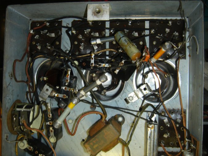
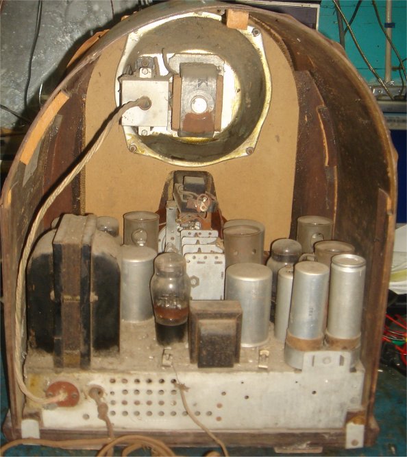
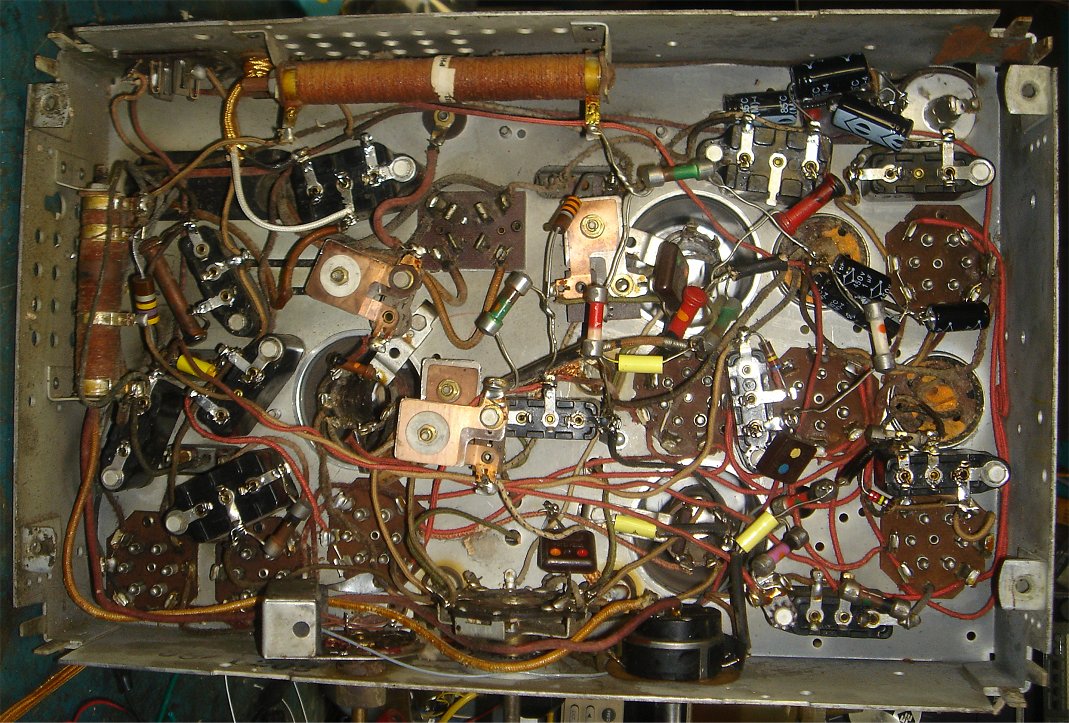
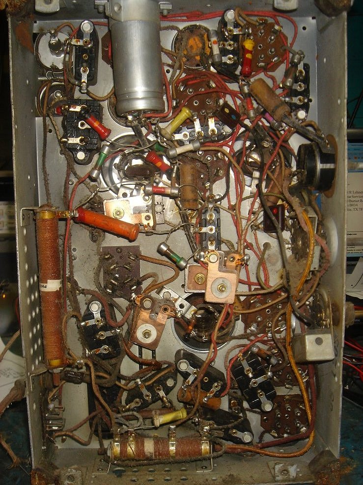
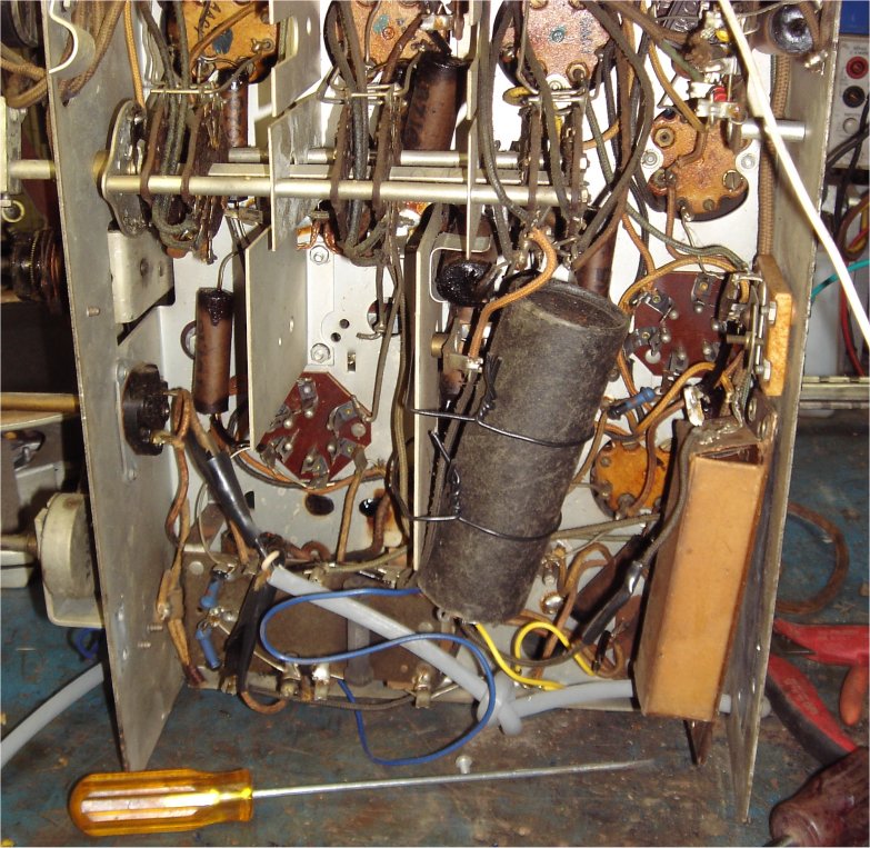
The chassis is complete. Everything looks original and no one has haked it through the years. My guess is: It sat in a barn for the last 50 years. I already removed the chassis, because it is the first step to a refurb. You can see the top of the chassis in the very first photo's. This is a look from the bottom. I can tell from looking at it, this won't be easy. I don't normally do this, but this radio is a little more complexe than most. So I decided to rebuild everyone of those baklite cap banks, and check the resistors as I go.
11/09/14
I did just as I said I would. Every one of those capacitor banks has been rebuilt. We carry every cap I used in this chassis. In the process I found an open resistor, and two drifted over 50%. These were replaced as well.
How did I rebuild the cap banks you say? Starts with writing down all the connections, then removing them. I used lacquer thinner to soften the tar, and that helps with the removal of the tar. With a small flat screw driver you can scrape out chunks at a time. DO NOT PRY unless your at the back end where the body screws on to the chassis. If you pry or put a lot of pressure on the sides or front, you will break the bakelite body.
11/11/14
I replaced the power cord and plug. I used the rayon cloth covers wire we sell , and an old stock plug I had hanging around. Powered up the radio and to my surprise it worked quite well. I thought it would need lots of tweaking and tube testing before this worked, but IT DOES NOT! HOWEVER the speaker does need a little work. Part of the paper surround is bad and there is a loud poping noise. Turns out the surround paper is very thin and needs to repaired. I will use clear silicon and spread it all arround the paper. This works great because the silicon seeps into the paper and makes it flexible and rugged. After doing this the poping sound was still present but the distortion sounds went away. I will need to apply silicon at the center of the speaker too.
11/13/14
Well the speaker did not work out at all. Yes it looks bad, but I don't care what it looks like. No one will see it! It sounded worst than before I touched it. This will need to be replaced.
11/15/14
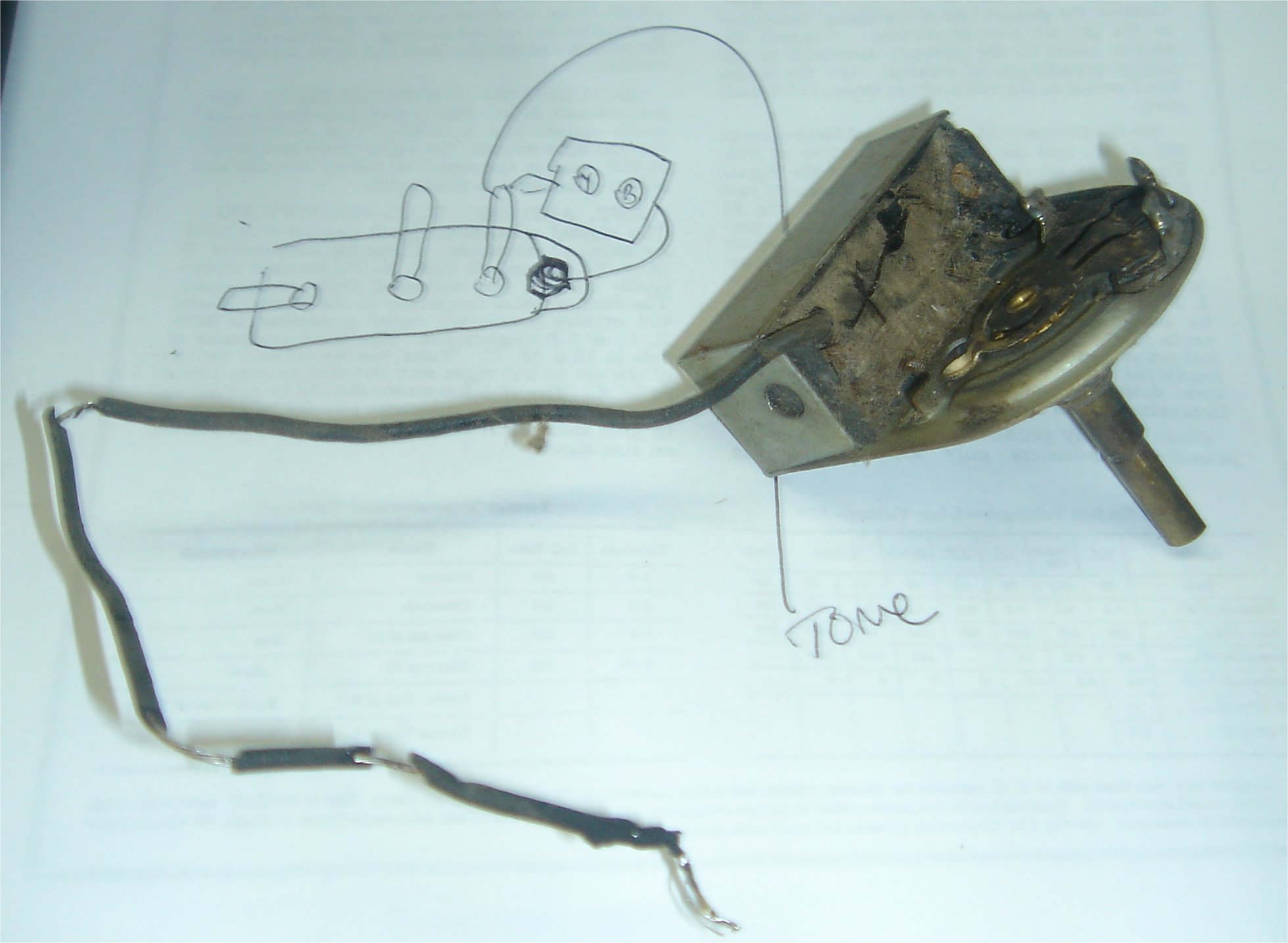
I rebuilt the tone
control because it wasn't working correctly. The wire fell apart when removing
it too. There are two caps in the same type of tar they used on the cap banks.
Once removed I replaced the two caps and the wire. I also had to clean and lube
the switch. When re-installed it worked just as it should. Looks like the volume
control needs some attention as well. These are great controls because they are
made to be serviced. All I had to do is remove the back and spray clean the
inside. I use WD40 and it has never let me down. This type of control needs a
cleaning and very light lube. It uses a piece of leather to press on a metal
band as it turns. The first picture shows the tone control as it is now. The
second is the volume control so you can see how it
works.
11/27/14
Back to the case: As you can see this is very bad, but lets take it to the limit. I realize going in this can never be perfect, but it can be a nice radio when done. The case as it is, can bearly stand up on its own, and is warped from the lose of structual intergrity through the years. The first thing to do is recreate the structual integrity before anything else is done.
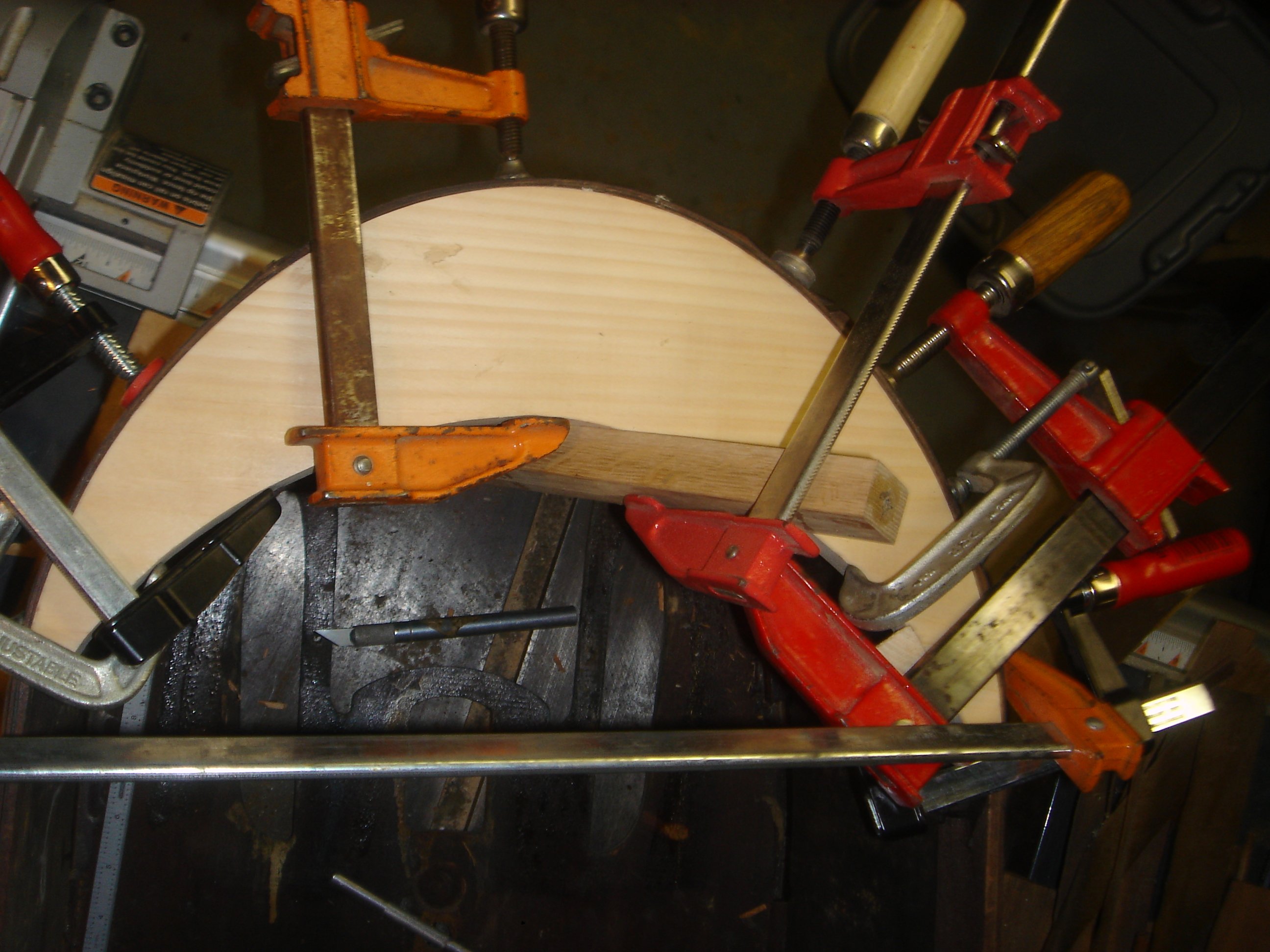
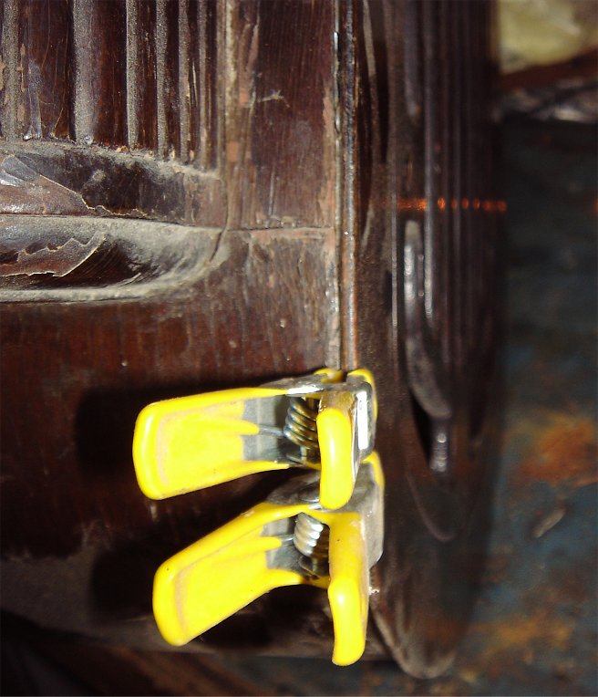
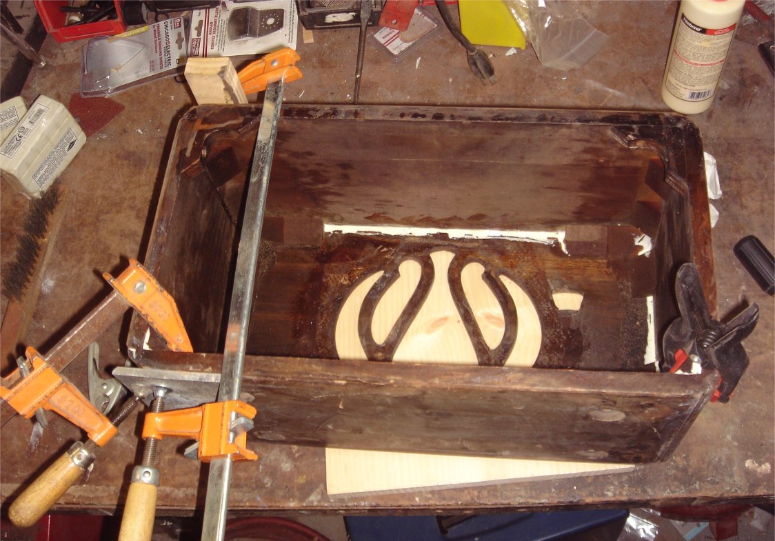
Two things: The front or face needs to be glued to the sides. A new rear crossmember needs to be made as you can see in the photo. This is solid pine and modeled from the front inside so the correct circular pattern can be made. A band saw and table sander makes this easier. The fit is great and it added so much to the strenth and integrity of the case. Now it is strong and looks great.
10/05/15
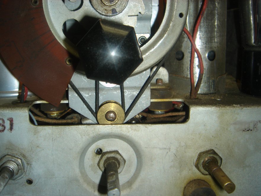
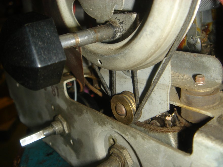
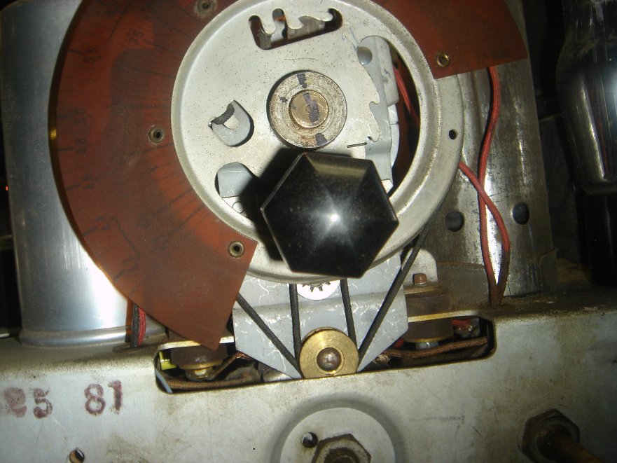
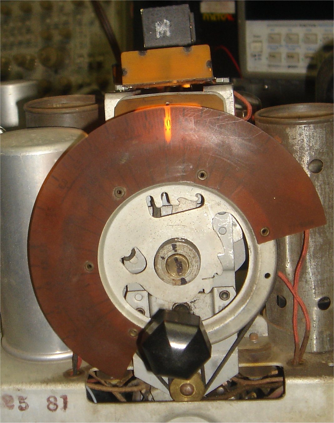
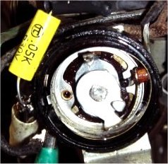
It has been a while, so this project has been on hold whaile I look for a chassis and speaker. I found one of each at the radio show a few weeks ago. Not sure if I mentioned this but the tuner mechanics is missing a couple parts, and the tuning shaft was missing. This is the weirdest tuning radio I have ever seen. This uses a dual brass pulley sending the string to the tuning shaft and the dial scale at the same time. Then near the tuning shaft is a second pulley? The new chassis did not have this second pulley and made more sense, but I still havent figured this out 100%. There is a couple photos below, one showing the original set up. The set up in use works well, but isn't exactly the same.
|
|
|
|
|
|
10/12/15
Now that the tuner hase been figured out, and the tuner shaft is installed I was able to complete the chassis. Also I did find a brand new reconned speaker for this set. I am in $75 of trade for capacitors, and $30 cash for both of these. However they play together very nice. The chassis and speaker sound great and work perfectly. The photo below shows what it looks like now. Althoguh I am sure you can't hear it, but it is playing right now. In any case it is ready to drop in the cabinet.
12/27/15
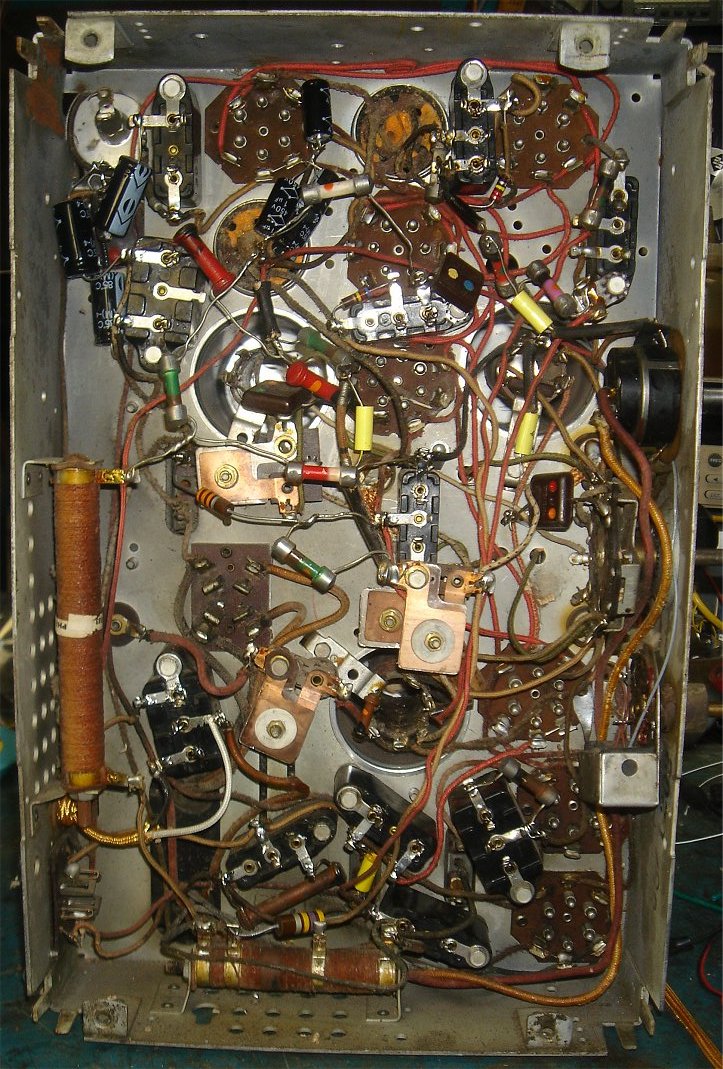
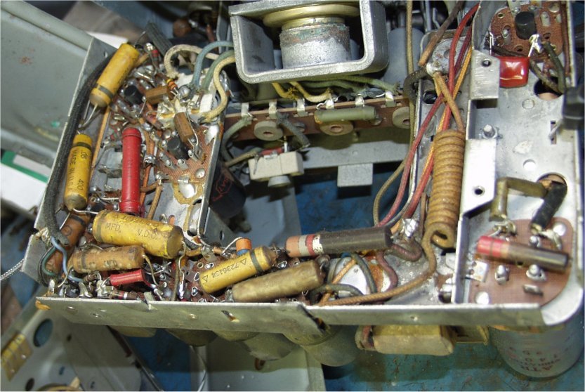
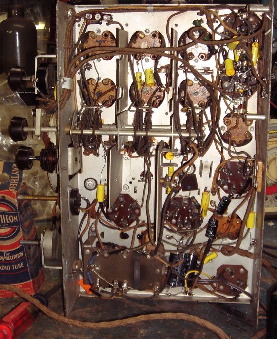
One of the projects that went to the back burner. I did a lot of work on the house this summer along with other things. Anyway I am on vacation and making the best of it. Started two new projects, and am on this one again. The chassis is ready to go. As you know from prior projects I do not pull the chassis apart and polish it up. I see no reason for that, unless yopu are going to put it in a Museum. However electrically and mechanically this is ready to go. Below is a picture of what the lower end of the chassis looks like now. I replaced many caps and rebuilt every one of those bakelite capacitor blocks. I also cleaned it up a bit. On the right you can see all the new electrolytic capacitors. What I like to do is leave the old cans in place on the top of the chassis. I disconnect them and wire in the smaller axial capacitors we sell. There is nothing worst than finding a radio with them pulled out already. Some people will gut them and put the capacitors inside the can. A nice idea, but not worth the extra time and effort. It doesn't make the radio play better, and if its a repair someone is paying much more than they should.
As you take out capacitors you can check the resistors. I had no open resistors, but a couple were out of range. If you look close you can see the three I replaced. In many cases you can connect a resistor sub box and tune for better perfromance. In the end the performance is amazing, and certainly better than original. So many of the resistors I replace are not the same value that was there to begin with. A little trick I picked up years back.
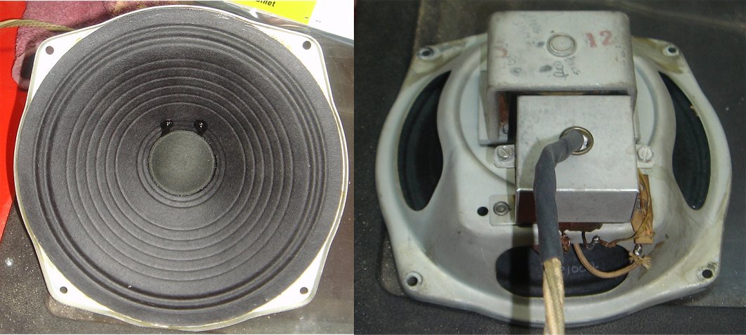
Below is the new reconned speaker. The front looks modern, but the rest is original as you can see in the photo's. Like most replacements the new speaker was not 100% compatable. I did have to do a little rewireing. This speaker was wired different at the speaker, and has a tapped matching transformer. This one also used three wires where the original used four. Not a big deal and I had to fix up the wire harness anyway as you can see in the right side photo.
12/30/15
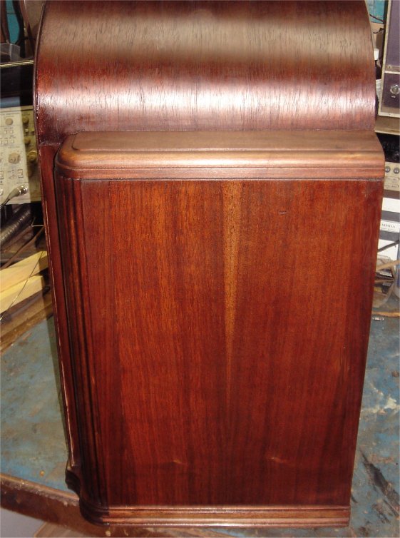
I did some more work on the case. It has many small issues that need a slow repeated process. There are waves and divots that need to be cleared up. Keep in mind the whole upper half was just about missing. The rebuild is a slow ongoing process done in layers. The good news is..........this is not far from complete. It will never be perfect, but it is a labor of love. When complete I will cherish it as it is. The good news is the case is very strong and just needs clean up work. The photo below shows what it looks like today. You have to admit quite an improvment from the original photo's. A little further down I will show some before and after pictures of the chassis and case.
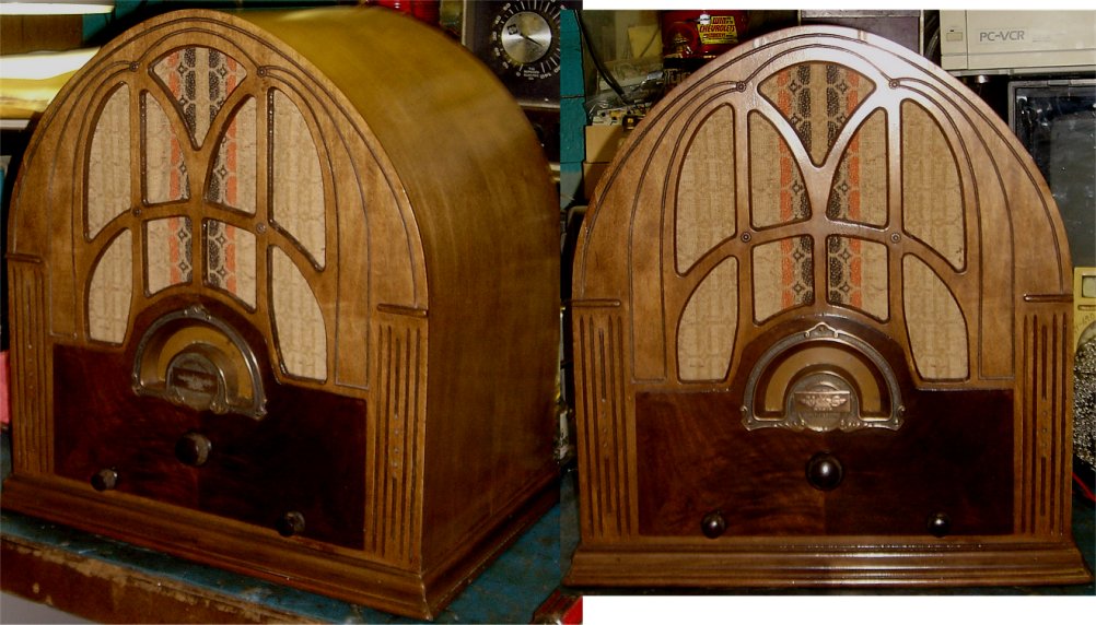
BEFORE and AFTER CASE

Lets compare the lower chassis. I have no problem taking cans out from under the chassis. This has no affect visually or ascetically from the outside. If you look close enough, you will see some parts are missing, some were moved, some removed. Plenty were replaced.
05/21/17
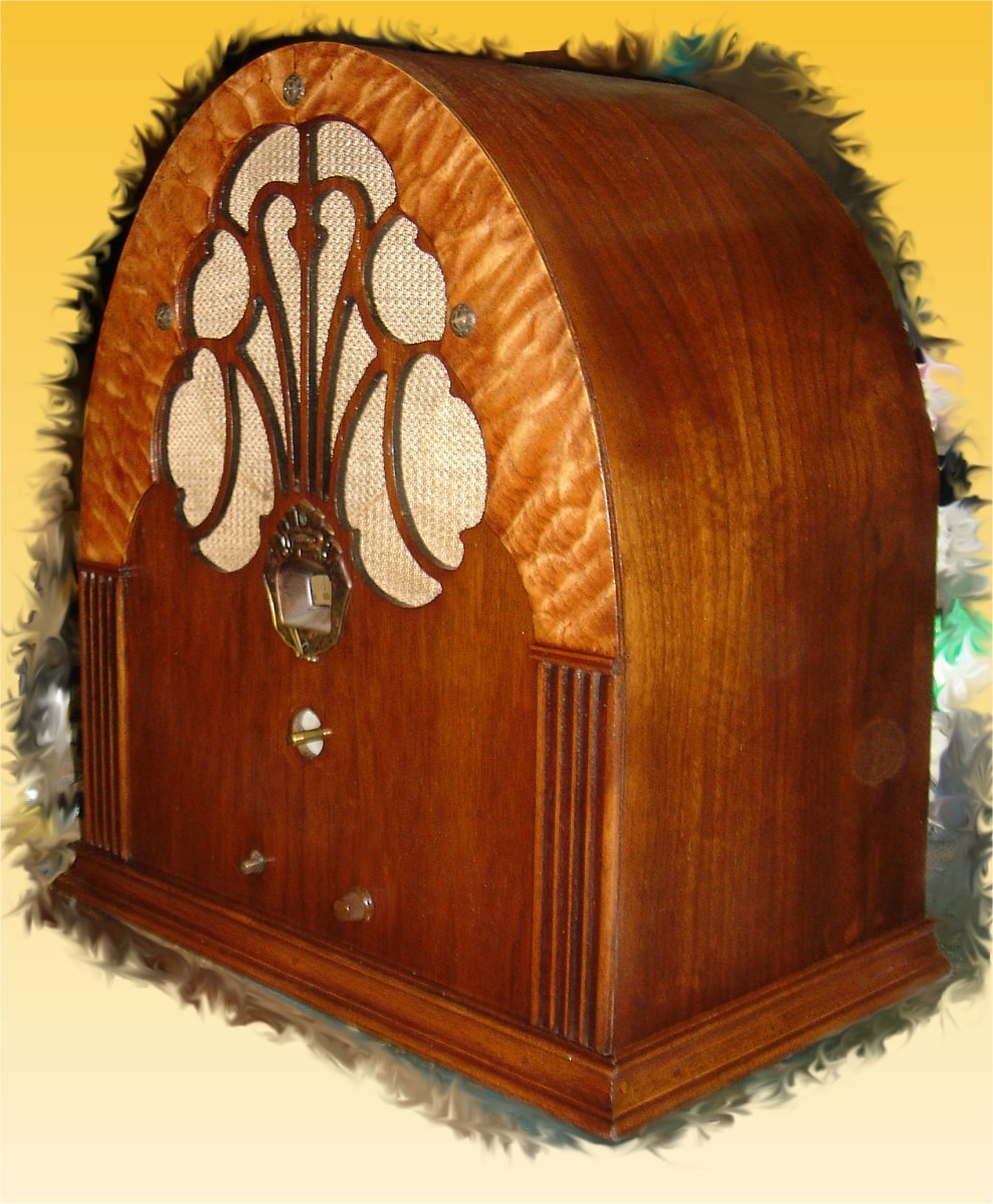
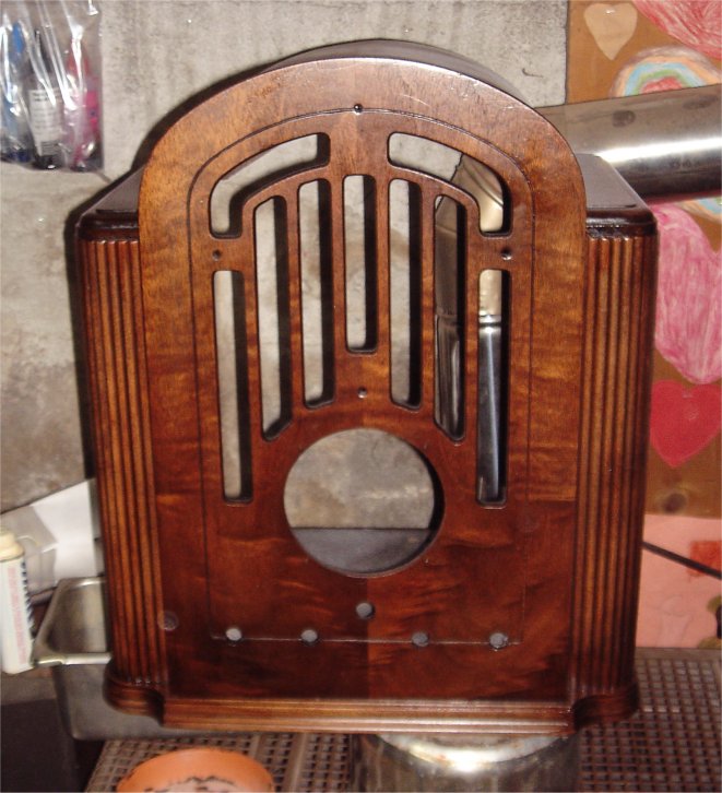
Almost forgot about this! Figured it out while updating this page. These are final pictures of the radio as it is today! Again a labor of love. Very many hours and certainly not perfect, but when I saw this I heard it yelling out to me, and had to buy it. YES, even at $60 it was not the best deal, but seeing it suffer like that.................. Something just wasn't right. Today it spounds great, works perfect, and is solid as the day it was made. Turns out these are hard to find too.. In any case ENJOY!
This is not an easy radio to get a picture of. I will try another with a better camera in the near future.
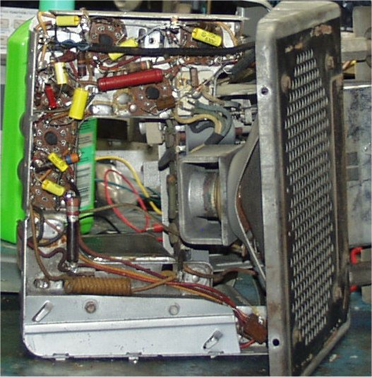
1955 Oldsmobile Car Radio 982697
06/24/12
I just rebuilt the exact same radio for a friend that has a 55 truck. I remember thinking to myself: I wish I had another car radio from the same period. I just love repairing the old car radio's.
Don't you think I found one a few days later at the flea market for $12.00
Like most of these sets, there are only two things that go wrong. Well one is almost always bad. Thats the mechanical multivibrator used to create the high voltage needed by the tubes. The other is just for good measure, and that replacing all the wax capacitors. It seems 99% of the time it is either the capacitors and/or the mutivibrator. As luck would have it, the multivibrator can be repaired most of the time. Capacitors can be replaced all the time. We have them all in stock.
06/30/12
Well guess what!
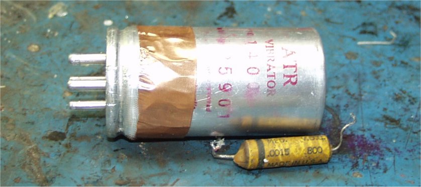
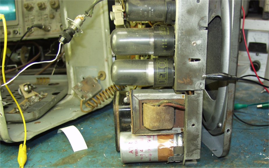
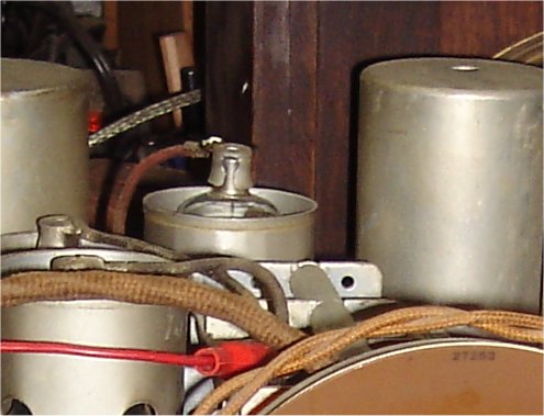
The multivibrator is bad, but the radio works great. I injected a 250 volt DC signal into the radio to find out. I will repair it and replace all the paper capacitors. Below shows what the chassis looks like now. I already replace the 1600 volt cap as you can see in the upper right hand side of the photo. I like to use the poly type because it delivers a little more performance in the way of voltage at the output, it is small and fits perfectly too. This is a very important part of this power supply. The stock capacitors range from .006 to .007uf in most radios like this. We stock the .0068uf cap to cover for both. Keep in mind the originals are 20% tolerance at best, and there nothing about precision in this circuit. The first photo shows a close up of the high voltage supply and the new 1600 volt cap. Now you can see the space limitations. There is a metal cover for this area too.
06/31/12
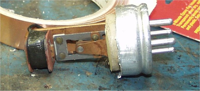
I cut open the multivibrator and repaired it. Like most of these, the contacts get corroded and/or need a slight adjustment. These run at about 110hz, so consider how hard they work in a few years. That's 110 times every second the radio is on. After 8 hours this has switched 6,660 times. Now consider an hour a day for a year 2,430,900 times. Not bad for an electromechanical device. So we shouldn't expect to much from them.
Anyway, a little emery cloth and an Isopropyl bath will get rid of the corrosion. Then a slight mechanical adjustment of the points and we got a working vibrator. Afterward you put the top back on with five minute epoxy and copper tape. The top picture shows you whats inside once cut open. The next photo shows it after the epoxy and copper tape has been applied. Not as pretty, but it saves you $40 - $50. I am working on a solid state design, and I will make a kit out of it soon to offer on my website. So please check back. Looks like the kit will cost about $15 and runs cool with FETs. It will also fits inside the original case.
07/02/12
The next photo shows the vibrator installed and working. The radio sounds very nice. Lots of power and a nice bass sound.
The vibrator works like new, and all the paper/wax capacitors have been replaced. Check out the chassis now! The next photo shows the top of the chassis. In the upper right side you can see two yellow capacitors I replaced. These are tone control caps soldered directly to the volume and tone control. The one below shows all the caps replaced on the bottom part of the chassis. You will also notice the metal cover over the 1600 volt cap and high voltage supply section.
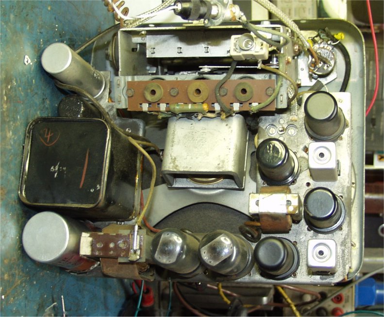
The next step is tune and grease the chassis. The manual tuning and semi-manual push button tuning is 100% mechanical. Just look for every moving point and add a small drop of oil. I use a heavy weight synthetic for these because it will not make the pushbuttons harder to push in cold weather. This will decrease wear on the mechanisms too.
Thats it for now. I am waiting for the parts to be delivered to build the prototype electronic vibrator for the kit. So this will stay apart and will be used to test the new kit before we sell them. I will clean up and polish the chrome once I reassemble the radio. I will update the web site too.
07/08/12
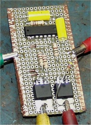
The parts did come in so I built the circuit on proto board.......................and................it didn't work. The picture below shows the proto board and connections to the radio. The square wave fades in and out, and the outputs from the FETS are always high. Now for some troubleshooting.
Did I mention I powered the radio back up at 24 volts and blew out every tube except one of the 6V6 outputs. So I had to repair the radio before I did everything else.
07/09/12
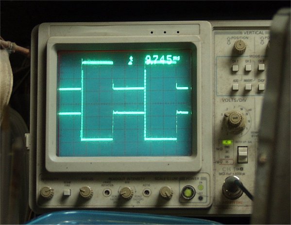
That wasn't to tough to figure out. This schematic is based off some I found on the internet. So I figured the final design was a go for sure. The first stage is a simple Astable Multivibrator. There are many ways to do this, but for space a one chip solution is best. This also help when designing a kit for resale. There was a grounding issue causeing the output to fade in and out. We now have both signals 180 degrees out of phase and strong. Check out the scope shot in the next photo. Of course this fixed one problem, and the scope shot was taken from the outputs of the chip. You may also notice the frequency is fixed at about 110 htz, just like the original mechanical vibrator.
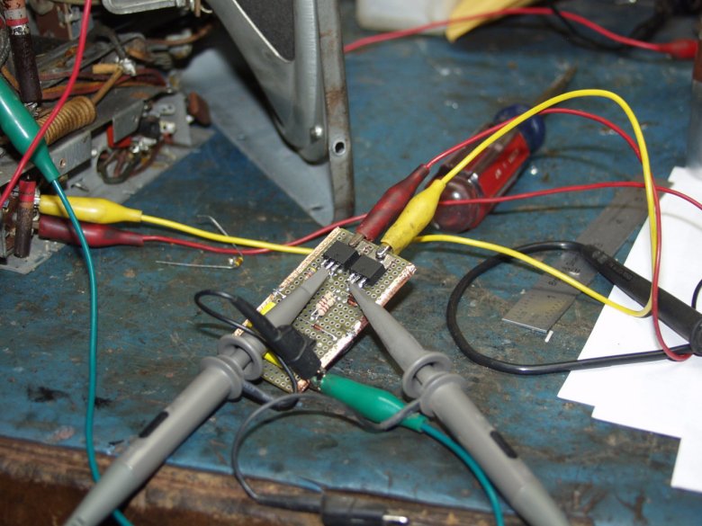
The second problem: Again a dumb mistake from me. I used P-FET's at the output stage thinking negative ground. The radio circuit is really using positive voltage at the step up transformer. Sooooo.............I had to install N-FET's to make it work properly. I also added a soft start self starting feature. This means it won't come on before everything is ready, and requires three wires minimum, instead of four. This is good news because radio's that use three connections will not require any kind of modification. This is now plug and play for the most common type systems. I ran this for a couple hours too. The FETS get warm and the output stays stable without heatsinks. Another PLUS! Check out the next photo! This shows the circuit working connected to the radio. Notice three connections, and after a couple hours the scope shot looks the same. If there was going to be overheating or thermal runaway it would have happened already. The radio is playing loud and clear. I am sure you can hear it in the photo.
******************************************************************************************
RCA 128
A very nice 6 tube three band radio. I am not sure if this would be considered a cathedral, or tombstone though. I found this a few years ago at a flea market for $60.
The chassis is complete, all the original knobs are here too. The dail glass and speaker grille cloth is also good. the cabinet has some major issues though. One side has lots of veneer damage. The edging around the front has a few dings. These are very hard to repair. To make it worst someone hacked up the cabinet with a very bad glue job. I will need to undo all that. In my experiance this also causes damage, but nececary to get this done right. Once again I took the chassis out before I took pictures. What you see below is the cabinet before the work. The damage isn't very appearent so I will show more details.
12/10/11
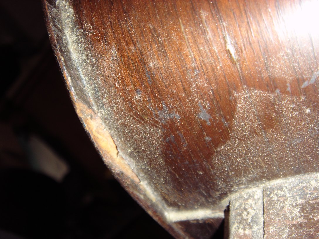
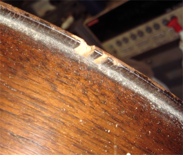
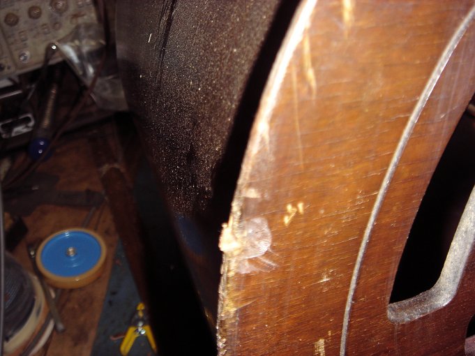
The pictures below show parts of the veneer damage in detail. On the right side in the picture below you can see dry glue. Someone tried to glue the font to the rest of the body some years ago. I will need to remove all this to fix it. This too may cause more damage to repair correctly. If it were left alone this job would be much easier. This also shows a chunk of veneer missing along the front edge.
Only one side has looks like this. The other is complete and looks good. These are pieces of missing veneer.
Another area of damaged veneer.
Another chunk of missing veneer. Actuall there are three in all, and a spot that was hit and dented in. The next picture shows the third area of damage.
12/13/11
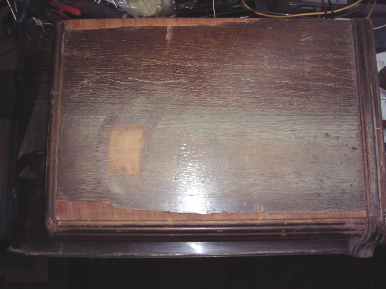
I will start with the side then work my way around the front edges. What I need to do is sand a small area to see the real color. This way I can match it to my scrap pieces of veneer from past basket cases. So save the old veneer! It is the only way to get a good match. I just throw the case outside for a week or two, and the weather does the rest. Assuming we get some rain. The picture below shows what I did and where I need to replace the veneer.
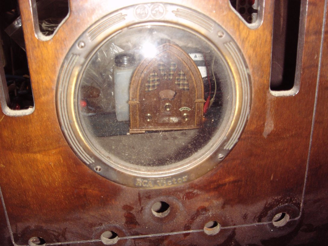
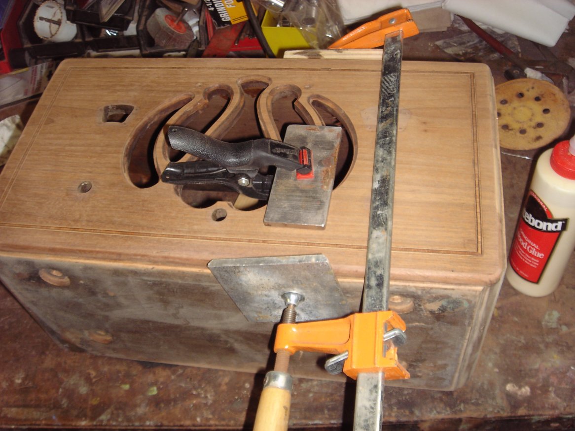
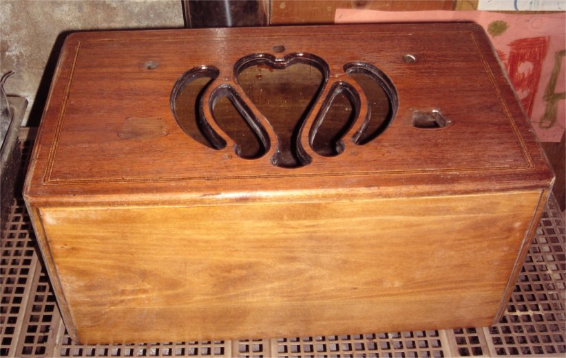
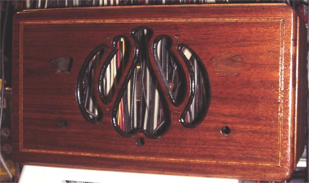
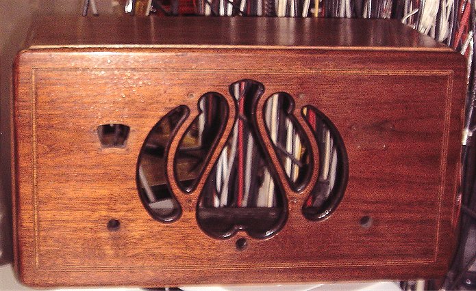
I took this picture to show a close up of the dial scale window. I wasn't going to add it until I noticed the radio behind the glass. This was not set up or intended this way. I happen the pick it up at a flea market recently. It isn't a radio either. It is a music box that looks like a radio. I just thought it was an interesting picture.
At this point I trimmed the original veneer to make a straight edge. I found a match in my pile of veneer too. What you see is the piece in place and clamped down while the glue dries. One piece at a time. Meanwhile lets start on the chassis.
12/15/11
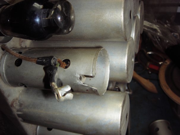
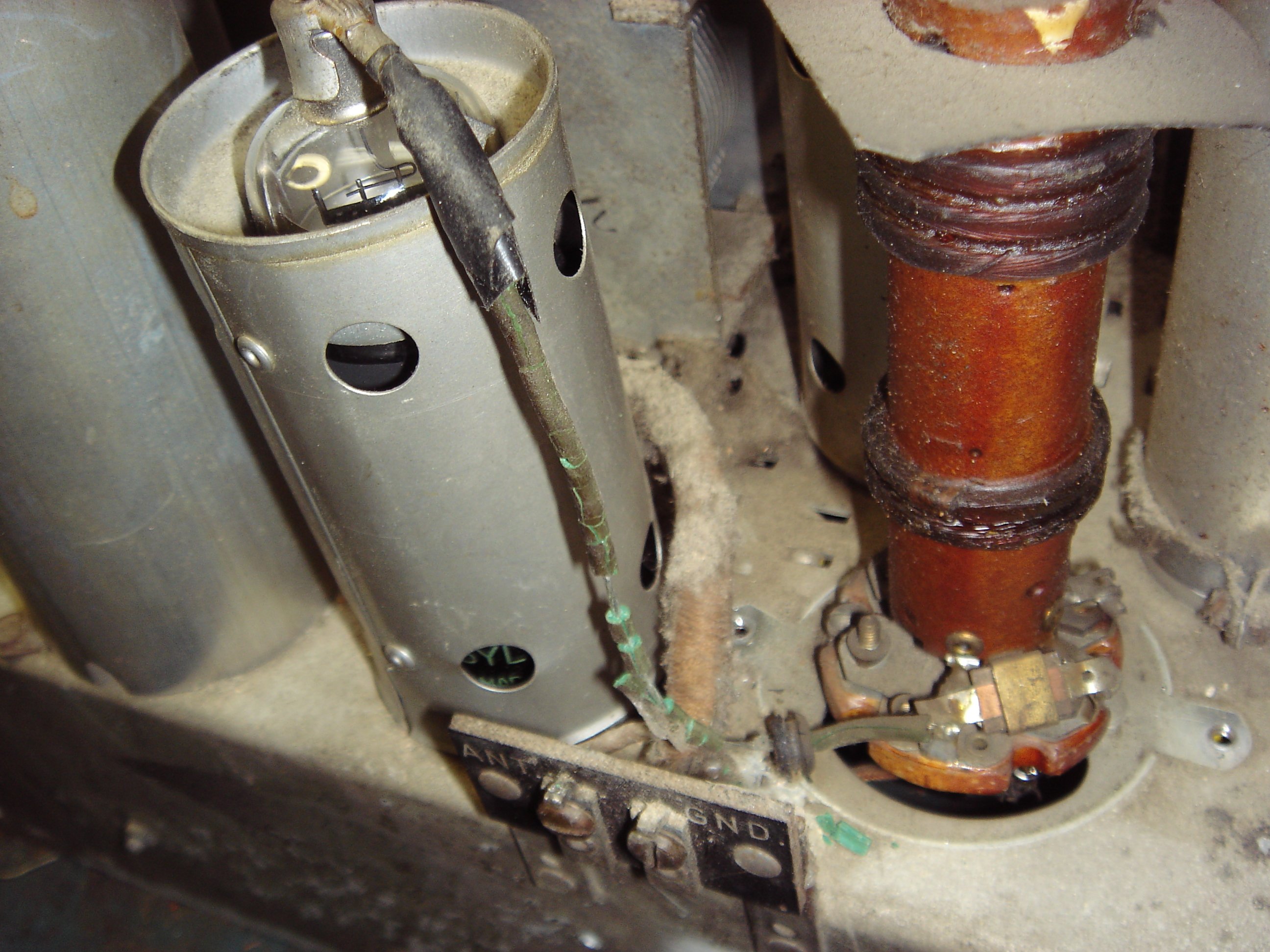
Like many radio's from the thirties, this has been hacked as well. I will never understand why someone puts an effort to do something wrong. There is nothing wrong with trying and learning from your mistakes, but intentional irreversable damage and just plain lazy efforts aren't the answer. Someone decided to cut out part of the tube shield instead of repairing the wire that connects to the top of the tube. They couldn't even fix the wire properly. The wire was supposed to go inside the can from the bottom. You can see the slot just behind the wire. Then they used electrical tape. You don't need to be a rocket scientist to know that isn't going to stay with all the heat produced inside. Take a look at the photo.
12/18/11
Meanwhile I figured I can repair the chassis from the bottom first. I have to say this is a pain in the @#%$##. None of the capacitors are marked, except for the RCA part number. I did get the free version schematic from Nolstagia Air online, but it wans't very clear. Although there is a parts list, none of the numbers match up to the numbers on the caps. So I purchased a schematic and it was no help at all. However the physical layout had all the info I needed. So I thought! It did get me about 90% there, but the tone didn't work and the volume control was at full volume or very little. We need to repair or replace that first.
12/20/11
Lucky for me this control can be repaired. This doesn't work like the average potentiometer. This one presses a metal band against the resistor. All this needed was a good cleaning. The back comes off easily with a solder iron. An acid brush dipped in Isopropyl Alcohol did the trick. Then a spray with WD 40, and it works like new.
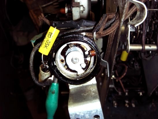
This picture shows what it looks like now. The solder area is the only thing holding the back on.
With this repair out of the way I can continue with a couple other probelms. T he output faded in and out at a certain volume. With a little research I found there were many versions, changes, and revs on the schematics for this model. So they were not 100% correct. Anyway a few hours later I found one of the caps in the audio circuit was the wrong value. I also found a wrong connection in the tone circuit. The current tone circuit does not match the schematic, but it works the way I connected it. A little tuning and all is GOOD, and what a performer. Nice loud and clear tone. The first picture below shows what the chassis looked like when I recieved it. The next piture shows what the chassis looks like now after all the hacks were fixed, and all the caps were replaced. I also removed all the extra wires.
BEFORE
AFTER
Back to the cabinet. I replaced and clamped the other half of the side missing veneer, and I sanded out the half I replaced already. It looks like a great match. While this dries I will repiar the damage around the front edge.
12/24/11
The next three pictures show various shots of the repairs. These are not 100% because they still need sanding and shaping. Once all this is done I will strip the cabinet finish. I find stripping after all the veneer damage is fixed helps match the color of the new veneer to the original. As you strip off the finish the old stain tends to flow evenly over all the surfaces.
12/25/11
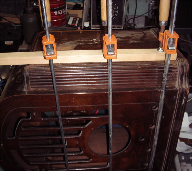
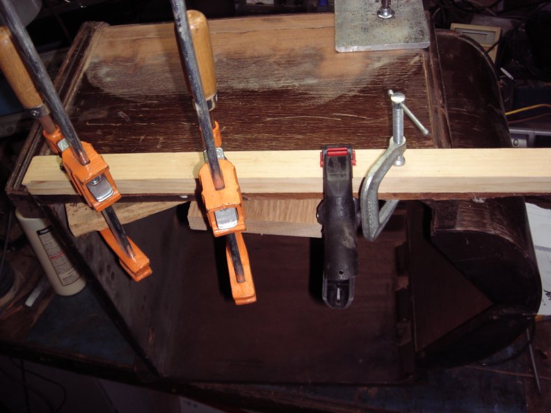
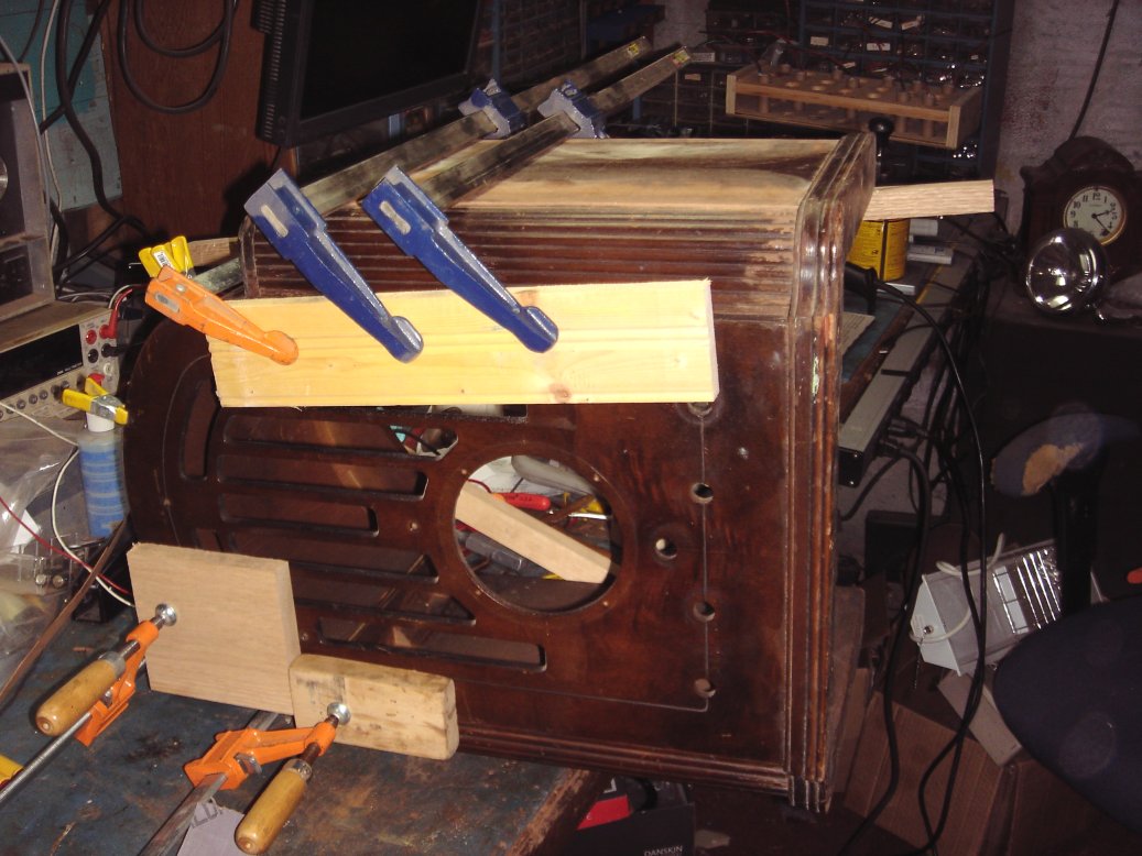
Mery Christmas! Well its late in the day and since I had a couple hours I figured I would find something to glue and set. I was able to push out the top part of the front panel enough to remove all the old glue in chunks with out damaging anything else. Now I can get it to line up with the rest of the cabinet as they should and eliminate the glue filled gaps. The problem with the glue comes through when you try to stain and paint over it. Soooooo more glue (correctly applied) and more clamping, but this will make a nice solid cabinet just as it was in the thirties. Since I could slide forward the upper half only with out damaging anything else, you can see why the boards and clamps were on the upper part of the face.
12/26/11
I did strip the cabinet. It will need a light sanding, then a dark stain. I don't want to show the veneer repair in the side right now because it doesn't look very good yet. It should all come together once I stain it. I had to remove some of the indents and deep scratches. This is done with an iron and a wet cloth towel, then some sanding and detail work where needed.
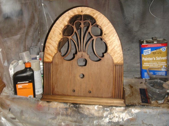
I have few days off so I should be able to finish this up soon. Meanwhile I have been listening to the chassis outside the cabinet. So far it has at least 10 hours on it. Today is stain day! This is where and when you can grade your performance. The picture below shows us where most of the veneer damage was repaired. The stain needs to be wiped down again and dried overnight. Then a detailed staining for the corners and inside edges.
This picture shows the front where most of the venner damage was around the front edge. This is shown after the stain dries though. You will have to get very close, then maybe you can see the repairs. Remember there was four places damaged.
12/27/11
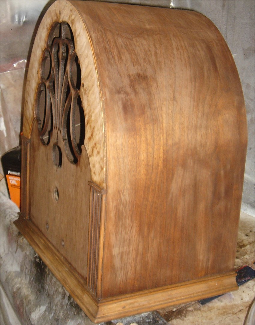
I decided to use a satin spray on laquer. DO NOT GET CHEAP WITH THIS! Use a good brand laquer. Spend the extra few dollars on a can from a good paint store. The picture below shows the first coat. I make sure to get inside and out with the first coat. This is sitting on a mild heat source with a fan overhead. I use this stove to heat the workshop too, so It serves a double purpose. When this dries, I will give it an inspection then another coat. This type of cabinet is very difficult to use the three coat and wet sanding tecnique. There are too many corners and details.
12/28/11
The next picture shows what we have after the second coat of paint. The picture does nothing for this radio though. It is amazing! What a beauty, nice dark rich wood tones.
Well now that the cabinet is done we need to get back to the top of the chassis. There were a couple hacks that included black tape and cut metal shielding. The picture below shows one of the repair jobs (hacks) that someone actually took the time to do this way. I used original cloth covered wire to repair this one and the others. One however was a shielded wire. That one I had to use modern type wire to get it right. The modern coax wire is balanced and shielded better.
You can see how authentic the repair looks in this photo.
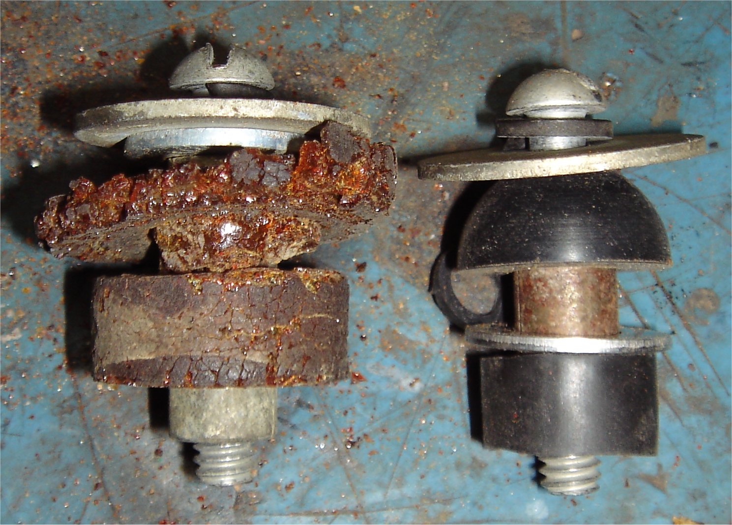
The chassis is ready and so is the cabinet. HOWEVER the chassis was floating on rubber cushings. I had to come up with a way to provide the rubber and make it work with the current hardware and mounting holes. The next picture shows what I found at a local hardware and automotive store. The tapered rubber part is a large water faucett gasket. The other rubber part is from a 3/8 inch water line hose for automobiles. A couple washer changes and we have a stack up that works great. The first stack up shows the original.
Lets finish up! The original grill cloth will go back in just as it is. The dial scale and original hardware will go back too, just as they were. The knobs will get a clean and shine before they are installed, and so will the dial glass. Take a look.............WOW!
Once again the pictures do not do this radio justice. One more thing to add though. A picture of the capacitors I replaced.
***********************************************************************************
11/11/11
I found this one at a flea market in the area. I bought it because it was cheap and an early thirties set. Also it was complete and in decent shape. The knobs were missing, but the dial scale and name plate were in tact. The chassis was complete too.
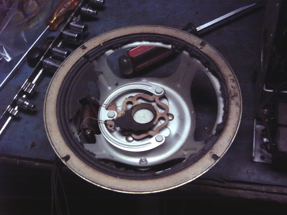
What are we up against! The speaker cone is gone. The chassis has been repaired by hacks, and the knobs are missing. There is no sound except for a slight hum in the bypass speaker I conncted. All the tube test good and there are no open coils.
The picture below shows the chassis condition just after I took out the chassis.
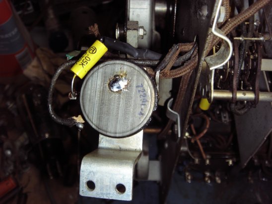
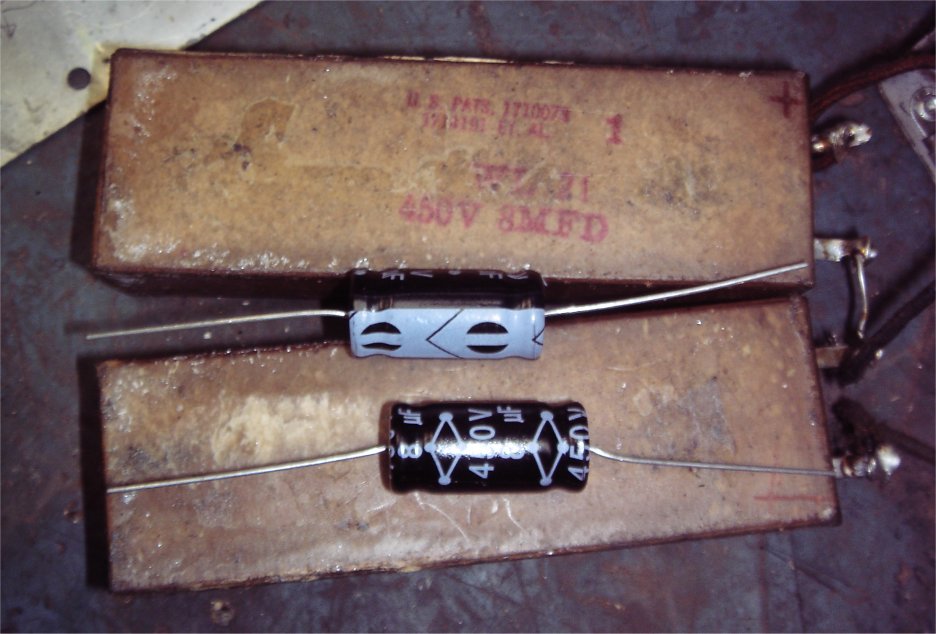
This picture shows the chassis at the time if examination. Someone made a bad attempt to repair this once before. They cut and soldered back all the parts they thought were bad. So I found some solder joints that didn't take, and a couple bad solder joints. After an inspection I did power it up. While measuring the voltage at the main power caps I noticed it would come up to 40 volts then start to go down. I also noticed the large box caps shown at the bottom of the chassis were getting hot. So at this point I knew these caps were bad.
This photo shows the original cap bank tied to a metal braket, and the replacement caps. Each box is stamped 8uf at 450 volts, so there won't be a problem getting the new caps to fit!
11/14/11
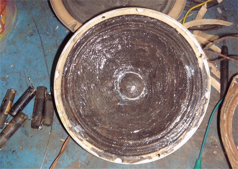
NOW FOR THE SPEAKER: I need to replace the whole cone. The rest of the speaker is good. I save speakers from other parts sets. I happen to have one i experimented on years ago. I covered the aging paper in clear silicon. Not very pretty but works and sounds great! So I took the cone off the other speaker and installed it on the original. This now works flawlessly, and does sound nice. The pictures below show before and after shots. Like I said not pretty, but it works and will out live me. Besides who is going to see the speaker?
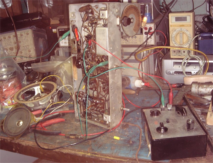
The rest of the chassis actually worked once the main power supply caps were replaced, but you can hear the oscilation. The next step is to replace all the paper caps, from our stock (www.radiocapacitors.com) then tune the coils, and set the tuner. The picture below shows the substitute speaker jumpered in place, and the decade box I used to find the correct capacitor for some of the unmarked caps.
11/21/11
The radio works well now! This radio produces a nice bass sound. I did have to replace/repair some other parts and lots of clean up. The other parts were cut and badly soldered. The picture below shows what it looks like now. A lesson: Do not cut the leads to test the part. Just replace the part. Lets face it, if the capacitor isn't bad right now it will probably go bad anyway. For 30 cents replace it.
11/24/11
As far as the top of the chassis goes I did clean that up too. I do not strip all the sockets and parts to sandblast the chassis. This is a hudge waste of time, and does not restore it to factory mechanical or electrical specs anyway. Just makes it look pretty. This one has been rusted due to a rodent, the same rodent that ate the speaker. I do clean it and the tubes. This is what it looks like when I was done. I also replaced the dial lamp from our stock (www.diallamps.com).
11/29/11
The cabinet has been stripped, as you can see below. I need to repair some of the damage, and sand out the blemishes. The cabinet is seperating in a couple places, nad the front speaker grill cracked where the screw holds the speaker in.
In the photo below shows where I had to glue in the blocks and glue the chassis where it was seperating.
The picture above shows the clamps used to press the new pieces of veneer in place while the glue dries. The next step will be a good sanding all around. Below you see the cabinet after the first coat of varnish, and after a wet sanding with 400 grit paper. This has been completly sealed inside and out with varnish. This is the best way to preserve the wood and good protection when wet sanding.
11/29/11
The next photo below shows us what the second coat looks like. This will need to be wet sanded again. Then we can use a polishing compound, and wax.
11/30/11
At this point the cabinet has another coat. This has been wet sanded, then a cutting compound was used. A good rinse in water, then a wax. This makes the cabinet very smooth and gives it a nice sheen, with a polished look.
12/03/11
FINISHED! I installed new speaker grille cloth, and some knobs. Installed the chassis and called it a day. The photo below shows what it looks like now. I did not polish out the dial scale or the name badge. I just don't like the look of them shinny. I like the aged look more.
DONE 12/04/11
*****************************************************************************************************************************
Gloritone
09/12/08
This is exactly how I found it at an antique shop.
The good things: It was painted many years ago when people didn't appreciate natural beautiful wood, and thought an antiquing kit was all that! WHAT WERE THEY THINKING?
I paid $40 for it in a booth that had a 25% off sale. Again the paint helps with the price, because it make items like this harder to sell. Another nice thing about the paint is the great protection it gave to the veneer.
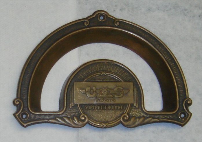
My initial finding: Well not to bad! Anyone want to plug it in? Anyway all the tubes are present, the speaker needs minor repair, all the knobs are present, and there is only a half inch spot where the veneer is missing. There is another spot where the veneer is lifting. Of course all the caps will have to be changed. I will test the tubes too, and replace the cord. I will do all this before I power it up.
One problem, and this is where the paint does not help. It will need to be stripped. That's two layers of the antiquing kit, then the original varnish.
For the cons: The tuning knob shaft is worn, but
still tunes. I will make a new one out of brass. The tuning dial is blank. I'm
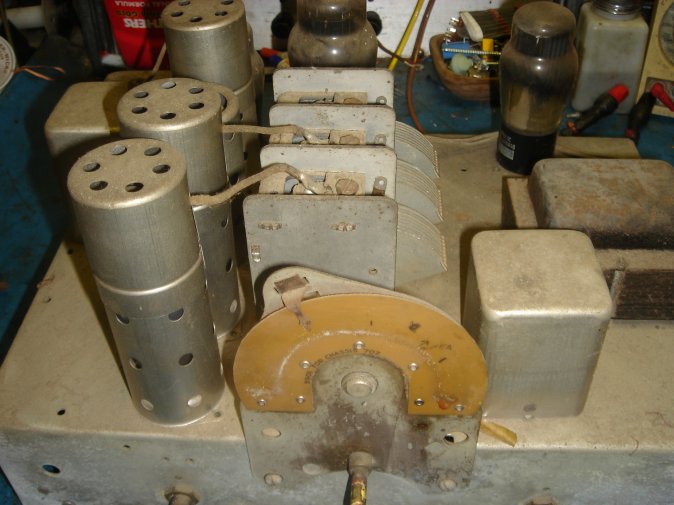
sure it faded through the years. I included a couple pictures of the chassis
below. If you know where I can get a new dial scale email me.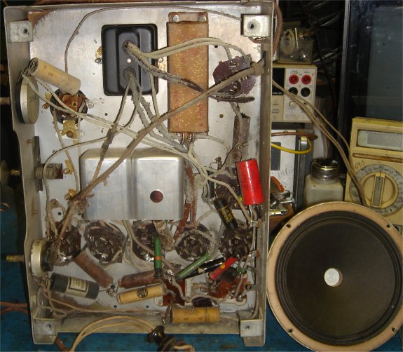
09/18/08
I didn't replace all the caps before powering up. I figured it would be better to know if it can be fixed before doing all the work replacing them. I did test the tubes though. All were good except the #48 tube was weak. I just wanted to make sure everything else was OK. I did replace the cord and powered up as is. The tubes light to, but nothing happens. I did some checking to find the transformer was good, but no output on the other side of the diodes (#80 tube). As usual a shorted capacitor was the problem, taking the B+ to ground. Take a look at the chassis picture above. The red capacitor was the culprit. So far I replaced the three major electrolytic caps in the power supply circuit. The red capacitor, and the long light yellow box above the red capacitor near the center. This is a double capacitor. I couldn't see the values, but knowing this is early thirties set I will use 10uf 450 volt caps from my stock and adjust if needed later.
Now the B+ is up around 385 volts, and the ripple is very good, so the 10uf caps were a good choice. However still nothing from the speaker. One weird thing though, and I have never seen this before. Inside one of the coil boxes there is high voltage arcing between the coil and the metal box. A little more measuring and I found that the coil is open. I am still not sure where or why the arcing though. It wasn't continuous either. Seems like it needs a little time to charge up.
09/22/08
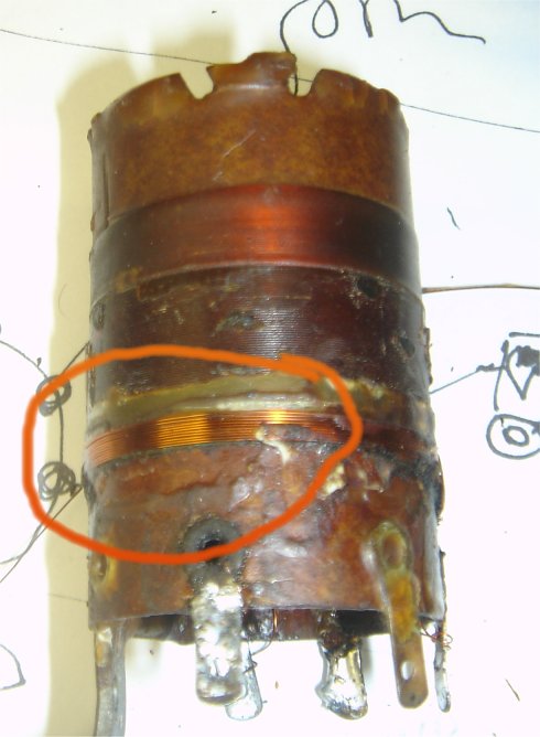
I found the coil in question is open. This is a lot
like the Philco coil in some of their early chassis. In fact I am willing to bet
these coils are interchangeable. The good thing though. Since I have wound so
many of them, I have the proper wire on hand. This is 0.0085" copper magnet
wire. YES, very thin! I was able to remove and rewind the coil with great
success. After reinstalling the coil and the rest of the capacitors we did get
sound. However very soft. For now I am a bit lost as to why. I don't have a
schematic though. I think I may need one to figure this out. I will
attach a couple photos later tonight.
09/28/08
Below is a photo of the repaired coil. I added
a circle where the new winding are.
11/12/08
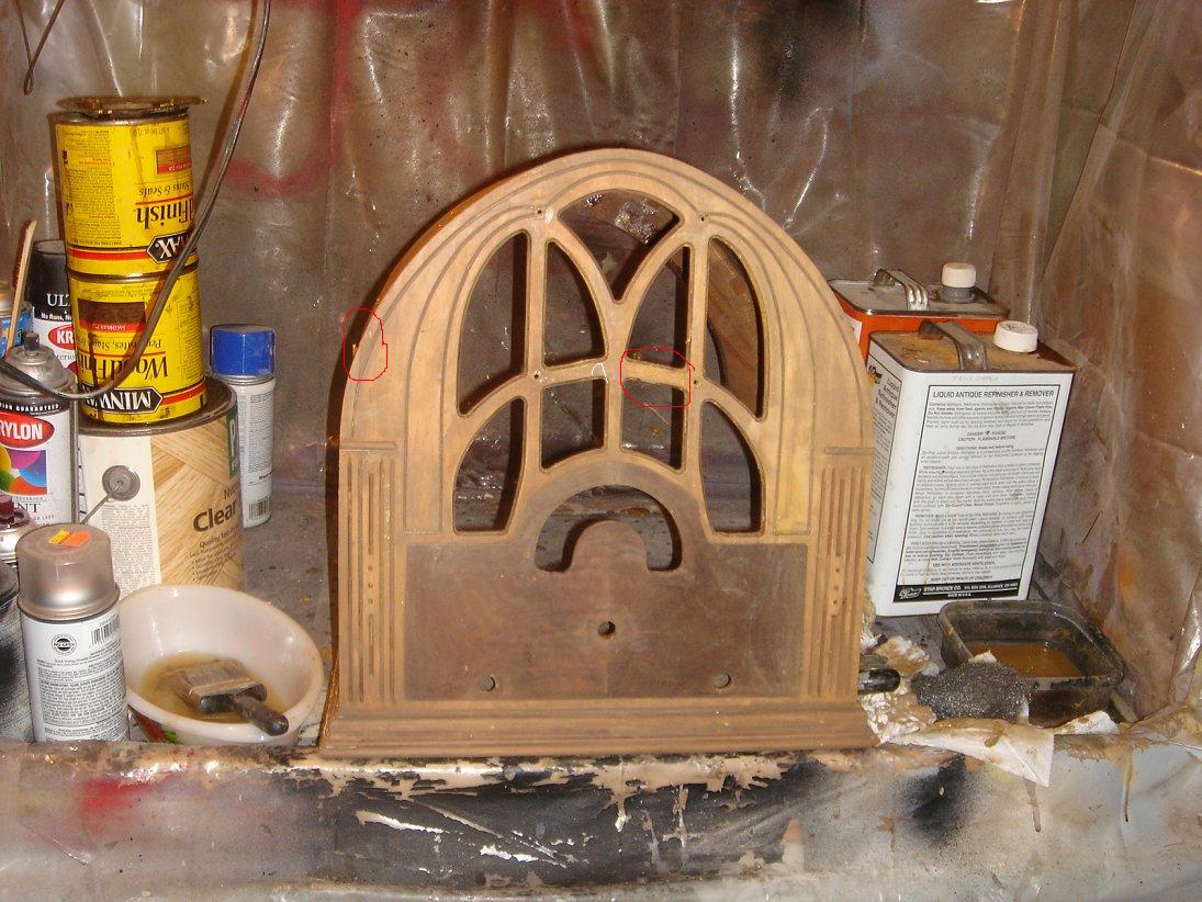
I finally got to the cabinet. I was right about the layers. There was the original varnish, then the base tan primer paint, then the yellow finish, THEN the antique paint. In the grille work there was some veneer coming loose. You will see it in a red circle. I had to pull it off at this stage. Also you will see another red circle. Thats where the veneer was damaged before I bought the set. The grille will be very easy to repair because I have those pieces. All that needs is glue and a clamp. The other has to be matched and spliced in. I will update with the repairs later. After removing the paint I see there is a lot of nice details under it. Check out both pictures.
11/15/08
The radio just got the first heavy coat of varnish. It will
need a couple days over the heat to cure.
11/24/08
This coat has been sanded with a 220 grit and painted
once again. Sometimes the first sanding will expose wood and cut some of the
stain away. It will also show any flaws. SO this is the step to make any
corrections. We need to use a tact cloth to remove dust and other particles
before we paint on another coat.
11/25/08
Now we sand again with a 220 grit sand paper. This
time we use more care. What that means is: We want to be careful not to cut
through the varnish. We want to stay away from corners too. We just want to make
sure the surface is flat and even. Then another coat in 24 hours. Don't forget
we need to remove dust and particles before we paint again.
11/30/08
The last coat has been applied and the radio has been
hanging over the heat since 11/26/08. The finish is done in steps. First we sand
with a 400 grit wet sand paper. Again we want to remove imperfections and insure
a flat surface. Then we use a standard rubbing compound, like Turtle Wax. We
make circles and use a wet soft cloth to apply, and rub until its gone. Then we
clean with a wet towel. The last step is a good wax. Once again I use auto wax,
like Mothers. The end result is a soft smooth finish.
DONE! 11/30/08
![]()
![]()
07/02/12