Capacitor Information, technical note.
Site Created 08/10/96 Page updated 05/01/25
Vintage Belt KITS Capacitors! Dial Lamps
|
Capacitor Information, technical note. Site Created 08/10/96 Page updated 05/01/25 Vintage Belt KITS Capacitors! Dial Lamps
|
|
What exactly is a capacitor, and how do we read
theses things? The basic
unit of capacitance is the Farad, named after the Michael Faraday.
Prior to the 1970's, capacitors were also called condensers. Same
part, same function, different name. You'll still hear the old name
used by some radio technicians. You will certainly see it in old
schematics. Capacitance is usually measured in microfarads abbreviated
uf, nano-farads (nf), or picofarads (pf). However, through the years
"uf" had many other acronyms. For example, a 40 uf may be read as 40
mF, 40 MF, 40 mfd, or 40 MFD. The unit Farad is used in converting
formulas and other calculations. A uf, (microfarad) is one millionth
of a Farad (10-6 F) and a picofarad (pf) is one-millionth of a
microfarad (10-12 F). A
capacitor is a device that stores an electrical charge or energy on
its plates. These plates are placed very close together with an
insulator in between to prevent the plates from touching each other,
and a type of dielectric. Usually a capacitor has more than two plates
depending on the capacitance or dielectric type. A capacitor can carry
a voltage equal to the battery or input voltage. Once charged the
discharge rate can be influenced by another source, such as a
resistor. This action can create oscillation, or be used for
electronic timing. The rate in which the capacitor charges and
discharges can be used to create a filter, or limit unwanted noise, or
used to prevent unwanted noise. There is lots more we can do with
capacitors too. They can also allow AC to pass through, or be used in
a DC circuit to eliminate AC, or AC noise. This would be called a
?bypass?. I guess you would really like to
know how to read all those different codes. Not to worry, it is not as
difficult as it appears. Some capacitors just tell you right out. Take
your electrolytic and large body types of capacitors: These usually
have the value printed on the body. For example: 100uf 250V, or
something like that would be imprinted in plain text. It would also
have marks pointing to the negative end of the capacitor. We cover
more information about this further down. I have seen some pointing to
the positive end, but only recently. That is not very common! So
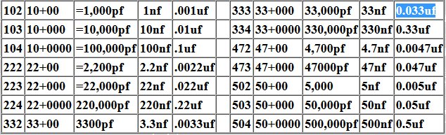
always pay attention, and use care. Start here for the smaller non-polarized
and old vintage and antique capacitors! It's mostly the smaller
caps will have two or three numbers printed on them, some with one
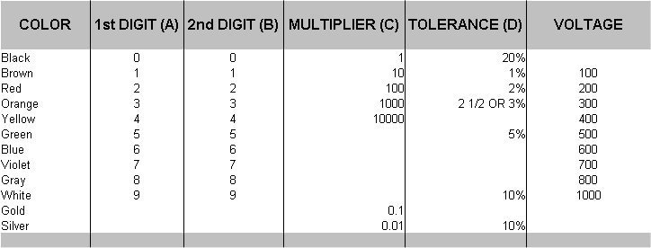
or two letters added to that value. Take a look at the table below.
This is a visual example, but not for all of them.
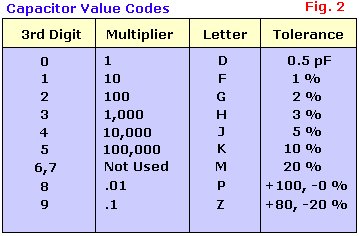
In most cases there is also a letter just
after the numbers. This is a tolerance code. Most are 5 (J) to
10% (K), but certainly not limited to just these two.
So
for example, it you have a capacitor with 474J printed on it:
47+4 zeros = 470000 =
470,000pF, J = 5%
tolerance. (470,000pF =
470nF = 0.47uf) The only
major thing to remember here is to move the decimal point back
six places for (uf) and three for (nf). Below in table A, is a
simple version for direct conversions to make it easier for you.
Now you know your capacitor is a 0.47uf 5% capacitor. Now your looking or asking about
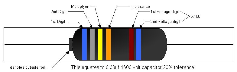
voltage! This is pretty straight forward. They dont code that on
most capacitors. The "bumble bee" type is coded with colors, but
they used the standard electrical code colors. Same as
resistors. This is covered later on on this page. The rest just
print it on the body. In some cases the manufacturer will put
ONLY their part number on the caps,
like RCA. That should be obvious because they make no sense, and can
not be decodes VIA electrical codes. Other capacitors may just have 0.1 or
0.01 printed on them. If so, this represents the value in
uf. Thus, 0.1 means just 0.1 uf. If you want this value in
nanofarads (nf) just move the decimal three places to the right
which makes it 100nF capacitor. Some caps will have a value then
a letter. For example .068K. In this case its a .068uf 10%
capacitor. In few circumstances the capacitor
may be marked in "pf" or "nf". However they should also in the
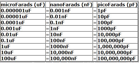
letter "p" of "n" at a minimum. The chart to the
right is a simple conversion chart. It will help you
understand how we convert uf to pf and nf.
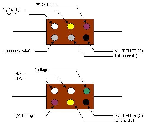
This chart below will help figure out
those codes on the Mica molded type capacitors. However, they
rarely go bad. I don't think I ever found a bad one myself. Keep
in mind this translates them to "pf" or "MMF". Don't worry they
both mean the same thing. This example below would translate to
47pf, or 47MMF. The example below shows two methods. These
are all I am aware of, and all I have ever seen. You must
use logic to figure out the starting point. If your capacitor
value starts off with 9 and a multiplier of 7, then there is an
issue. Most of these are basic value
capacitors. Please note the "N/A" positions may have no
color, and this goes for any spots that mean nothing or does not
apply.
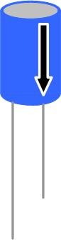
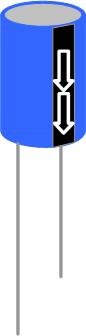
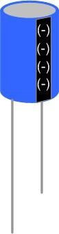
Lets start with two of the most
common: Radial (wires coming out the bottom) and Axial (wires
coming out the sides). Also note the shorter lead coming from
a radial capacitor is the negative end. So if there
are no markings, then you will know the shorter lead is the
negative end. In the examples below you will notice five
different ways to show polarity. There are more, but I think
this will be enough to get the point. The arrows and stripes are
"almost always" present. You will find many variations of this
as well. They always depict the negative lead. What is almost always: Good question............In
rare cases, long before there was a standard
format you may find that positive end is marked. With
multi-caps the information is on the body either by wire color,
or a basic shapes imprinted by the leads. Shapes are usually a
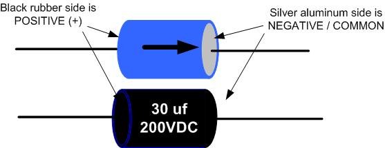
square, or triangle. In
these examples below you will find an added way to figure out
the polarity for axial capacitors. Remember these are marked
with arrows and strips just like the radial caps. Almost always
pointing to the negative end. On axial caps though, we can find
the polarity just by looking for the aluminum housing. The
aluminum housing is almost always the negative end. The other
end will have a rubber seal, sometimes epoxy or glass, but
always insulated from the housing. If you see no marks, or both
sides are insulated, then you may have a non-polarized
electrolytic capacitor. You would find these in crossover
networks, speakers, and some amplifier circuit boards. Other
than that, this should help for 99% of
them.
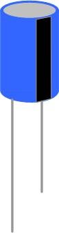
NOW, a couple things about capacitors with
out a polarity!
Take a look at these below. The first one has no markings at
all. This is normal for non-polarized axial capacitors. This is
the most common type found in early radios, and televisions. As
well as most early electronic devices. They used
paper and oil as a dielectric, then dipped them in wax. The
new capacitors use a metalized poly film, and dip those in
epoxy. AKA a dry capacitor. The new one will never dry
out on you, will last your lifetime PLUS, and will perform just
as good if not better than the original. The next capacitor
is basically the same except they do have a mark for a
polarity. Not necessarily for Positive and Negative. This mark denotes which side
is connected to the outside foil. The mark will be a stripe running
all around the body of the capacitor. The reasons
for the marking has to do with coupling in Hi Fi
amps. If you use these correctly they will cut down noise generated
internally in the amp. You would want to connect the marked end in
a special way so the out side foil doesn't interfere with
another component, or send picked up noise to ground. Or can
help eliminate interference from other components. Most people call these audio caps,
because they are primarily used in critical, or
high end amplifier circuits. However, the new caps
and new technologies eliminated the need for this outer foil marking.
Going forward you can replace a capacitor with a
stripe with a capacitor that does not have
one.
Electrolytic: Many questions about what
values can be used when replacing an old capacitor. Actually, the
exact replacement value should be close. In most circuits the
value can be doubled, or half. For example, a 12uf (microfarad)
capacitor can be replaced by a 10uf or 20uf. I would go with a higher
value before a lower one though. However, in a power supply you do not
want to go to high. The inrush current coming from the transformer may
damage or burnout the transformer, or rectifier. This is more
important as we go back in time when we used higher voltages and lower
current. What most people dont realize, is capacitor tolerance back
before the fifties was very high. As mush as 100%, or +/- 50/80% on
many high value electrolytic filter caps. Although the original is
marked 4uf, it could be 1-8uf when measured. Through the ages who
knows what value it is 50 or 80 years later. Typically, your best bet
would be to stay within + or - 20% of the original value. One thing
you will find with values and time is the capacitance
of the power supply caps. Radio's from the twenties used 600 volt
1-4 uf caps. In the thirties they used 10- 20
uf caps at 400 volts. The fifties they used 50-100uf at 150
volts. As time goes on the electronics got more efficient due to Engineering and technologies.
The older sets used more voltage and less current. Thats why the caps were smaller.
This could be due to cost too. The point I want
to make is about the caps getting larger in value through time.
When AC current is rectified VIA a diode the capacitor is used to
take out the ripple and make the DC voltage as
clean as possible. The less current you use the smaller the capacitor has to
be. Yet not affected by voltage. Keep in mind that
Ohms law is still in play. Less current but more voltage, as apposed
to low voltage high current. Both of these power supplies can deliver the same
power though. Just an FYI to keep you thinking. Non-polarized: These are very much like
the electrolytic with one exception. These should be closer matched. I
would keep these within + or - 10%. I am sure 20% will work for most
applications, but there are usually a few tighter tolerance caps
in the device originally. As you go back in time those would be
Mica caps because they are easier to manufacture with a tighter
tolerance, and they are super stable, meaning the value is
accurate as temperature, humidity, and other outside influences. So
10% should cover all of the paper type, and make it easier to adjust
the device when done. Never replace a capacitor with one
rated below the original capacitors voltage!
HOWEVER, a replacement rated above the original value is
acceptable. That's about it. If the original value is 350 volts, then
any voltage rating higher is acceptable. The voltage rating on a
capacitor is a maximum value. A 400-volt, 450-volt, or even 600-volt can
be used to replace a 350 volt capacitor. Another thing to consider the
new capacitors have a much higher tolerance to to over voltage
spikes. Sometimes when you turn on a device the voltage may be
higher for a short time period, then settle in the normal operating voltage.
Just a point to make you realize its OK to use a
450 volt cap in a circuit the reaches 600 volts for a second or two
as long as the device runs under 450 volts normally. Capacitors are designed to handle
this.
USE UP THE CAPS YOU ALREADY HAVE
Here are a few other things you can do with capacitors. This is
great if you have capacitors already and don't need to spend the
extra money on more! In example 3.1 you will see how we can make
a 50uf cap from two 25uf caps. Any of the values will add
together, BUT not voltage. Notice the voltage values are
different. In this case the total voltage can NOT be higher then
the lowest voltage value. This is now a 50uf, 160 volt
capacitor. Now take a look what happens when we add a
third capacitor.
Example
3.1 Example 3.2 is now a 100uf 160-volt capacitor. I guess
you got the point by now. This is called a parallel design. Just
remember capacitors add up in this configuration. Example
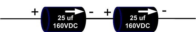
3.2 Now lets make a 12uf out of two 25uf capacitors. What we want
now is a configuration that divides capacitor values. Simply put
Series configuration. This can be used for the same reasons as
the parellel version above, but also to double the voltage. In
this configuration you should use the identicle caps and
voltages. This way the internal resistance and other parasidics
are equally matched, or at least close. Example 3.3 will show a
12uf 320 volt capacitor. So you lose capacitance, but you gain
voltage. I wouln't go further than two, and in delicate or
sensative circuits i would stay away from this. For most
situations this works perfectly. Example 3.3
Most antique radios failures are due
to dried out CAPACITORS. Most capacitors are made with
foil and a dielectric. As time goes by the material used
as a dielectric can dissipate from the body of a
capacitor, causing it to fail. Sometimes they short
causing other failures, but most of them just OPEN-UP. The
electronic circuit acts as though the capacitor isn't even
in the circuit. Just replacing a couple capacitors can
repair most antique radios. You may hear nothing, or you
may experience a loss of selectivity and/or sensitivity.
This will help to explain why for a couple bucks you can
repair these problems yourself with a few capacitors!
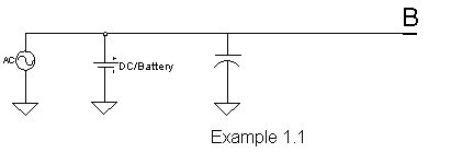
The example below
is an example of a simple bypass example in an ideal
situation. This circuit will allow the DC to flow, but not
the AC. In simple terms a capacitor will see AC as a short
circuit. The example below could be used
as an input signal conditioner on an amplifier. Blocking
DC, which can damage your speakers as well as your amp.
However it will allow AC or audio (AC in many frequencies)
to pass. If it were to open then nothing would get
through. Or the output may sound weak and distorted.
Remeber a capacitor sees AC as a short circuit,
so DC sees a capacitor as an open. SOOOO, why use
capacitors in a DC circuit? One reason we already know. To
block AC and or noise. If we read the previous Tech Notes,
we also know they are used to filter DC. With a couple
more components we can use capacitors for oscillators,
band pass filters, and so on. We won't go that far. I want
to keep this simple to insure it could aid anyone.
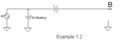
This circuit will allow the AC to go
through, but not the DC. Just the opposite as the circuit
above. The information contained within this
website www.wjoe.com, or any affiliate, is derived from
theoretical information based on experience and knowledge
obtained in experiance. The reader "you", are ultimately
responsible for any and all information used from this site. Any
damage, or any consequences you experience from this information
is solely your responsibility. This information is a free
service, so please enjoy it! Any other use, retention,
dissemination, editing, selling, or copying anything from this
site, for any intent is strictly prohibited. Unless you obtain
written permission by me at joe@wjoe.com. Any information on
this web site is owned by myself and is intended to aid you in
your research about Antique or Vintage capacitors. Please
enjoy!!!!!!
Written by WJOE Radio 08/10/96, LLC Edited
05/10/25


![[Image]](http://www.wjoe.com/capacitor_pics/electro_parel_examp_3_1.jpg)
![[Image]](http://www.wjoe.com/capacitor_pics/electro_parel_examp_3_2.jpg)
Now
lets review.
Always
watch your voltage ratings! Always watch your polarity (notice
the + on all my examples) these are called electrolytic
capacitors because they have a polarity.
Be sure
you discharge your capacitors before you handel them.
![[Image]](http://www.wjoe.com/capacitor_pics/fltpict3.jpg)